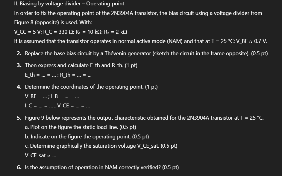
Question: Il. Biasing by voltage divider - Operating point In order to fix the operating point of the 2N3904A transistor, the bias circuit using a voltage

Il. Biasing by voltage divider - Operating pointIl. Biasing by voltage divider - Operating pointIl. Biasing by voltage divider - Operating point
Il. Biasing by voltage divider - Operating point In order to fix the operating point of the 2N3904A transistor, the bias circuit using a voltage divider from Figure 8 (opposite) is used. With: V CC = 5 V; R_C = 330 0; R1 = 10 kQ; R2 = 2 kQ It is assumed that the transistor operates in normal active mode (NAM) and that at T = 25 .C: V_BE = 0.7 V. 2. Replace the base bias circuit by a Thevenin generator (sketch the circuit in the frame opposite). (0.5 pt) 3. Then express and calculate E_th and R_th. (1 pt) Eth = ... = ... ; R_th = .. = . 4. Determine the coordinates of the operating point. (1 pt) V_BE = ... ; I_B = .. = ... I C = ... = ... ; V_CE = .. = . 5. Figure 9 below represents the output characteristic obtained for the 2N3904A transistor at T = 25 .C. a. Plot on the figure the static load line. (0.5 pt) b. Indicate on the figure the operating point. (0.5 pt) c. Determine graphically the saturation voltage V_CE_sat. (0.5 pt) V CE sat ~ ... 6. Is the assumption of operation in NAM correctly verified? (0.5 pt)O Vcc R 1 RC C B E R2 Figure 8\f

Step by Step Solution

There are 3 Steps involved in it

1 Expert Approved Answer
Step: 1 Unlock blur-text-image
Question Has Been Solved by an Expert!

Get step-by-step solutions from verified subject matter experts

Step: 2 Unlock
Step: 3 Unlock

Students Have Also Explored These Related Accounting Questions!