

Figure 1 illustrates a common emitter amplifier using BC547. Calculate the resistance of R1, R2, Rc and
Question:
Figure 1 illustrates a common emitter amplifier using BC547. Calculate the resistance of R1, R2, Rc and Re to make an emitter current of about 1 milli-amp by using the design notes below.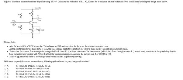
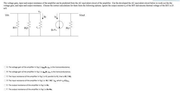
The voltage gain, input and output resistance of the amplifier can be predicted from the AC equivalent circuit of the amplifier. Use the developed the AC equivalent circuit below to work out the the voltage gain, and input and output resistance. Choose the correct calculations for them from the following options. Ignore the output resistor r0 of the BJT and assume thermal voltage of the BJT is 25 mV.
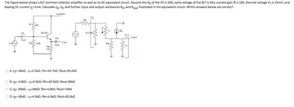
The Figure below shows a BJT common collector amplifier as well as its AC equivalent circuit. Assume the RS of the FG is 50Ω, early voltage of the BJT is 45V, current gain β is 100, thermal voltage VT is 25mV, and biasing DC current IC=1mA. Calculate r0, rπ, and further input and output resistances Rin and Rout illustrated in the equivalent circuit. Which answers below are correct?
Expert Answer:


College Physics Reasoning and Relationships
ISBN: 978-0840058195
2nd edition
Authors: Nicholas Giordano
