

Question: Implement the finite state machine (FSM) described by the state transition diagram below. The FSM has 5 states (S0-S4), 1 input (W) - as well
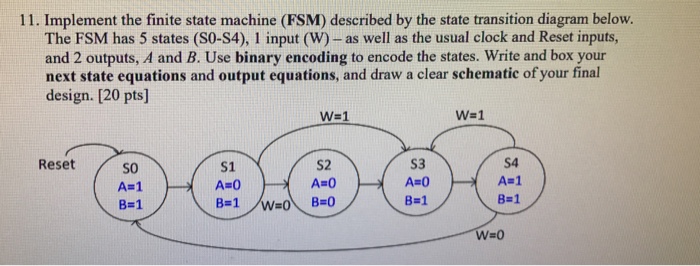
Implement the finite state machine (FSM) described by the state transition diagram below. The FSM has 5 states (S0-S4), 1 input (W) - as well as the usual clock and Reset inputs, and 2 outputs, A and B. Use binary encoding to encode the states. Write and box your next state equations and output equations, and draw a clear schematic of your final design. Implement the finite state machine (FSM) described by the state transition diagram below. The FSM has 5 states (S0-S4), 1 input (W) - as well as the usual clock and Reset inputs, and 2 outputs, A and B. Use binary encoding to encode the states. Write and box your next state equations and output equations, and draw a clear schematic of your final design
Step by Step Solution
There are 3 Steps involved in it

Get step-by-step solutions from verified subject matter experts