

Question: Implement using Verilog a circuit that accomplishes the following: Implement the Function unit(Red circle), Figure 7-9 Show simulation results (Modelsim or ISIM) to prove your
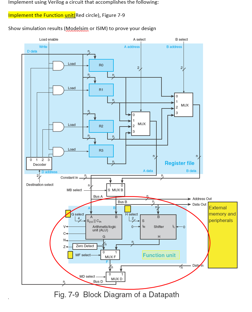
Implement using Verilog a circuit that accomplishes the following: Implement the Function unit(Red circle), Figure 7-9 Show simulation results (Modelsim or ISIM) to prove your design Load enable A select B select A address Write B address D data Load RO Load R1 MUX MUX 2 Load R2 3 Load R3 0 1 2 3 Decoder Register file B data A data D address 2 Constant in - Destination select n. S MUX B MB select Bus A Address Out Bus B Data Out External memory and peripherals G select H select S20|| Cn Arithmetic/logic unit (ALU) 0 IR V+ Shifter 0- C+ N+ Zero Detect Function unit MF select- MUX F Data in MD select MUX D Bus D Fig. 7-9 Block Diagram of a Datapath Implement using Verilog a circuit that accomplishes the following: Implement the Function unit(Red circle), Figure 7-9 Show simulation results (Modelsim or ISIM) to prove your design Load enable A select B select A address Write B address D data Load RO Load R1 MUX MUX 2 Load R2 3 Load R3 0 1 2 3 Decoder Register file B data A data D address 2 Constant in - Destination select n. S MUX B MB select Bus A Address Out Bus B Data Out External memory and peripherals G select H select S20|| Cn Arithmetic/logic unit (ALU) 0 IR V+ Shifter 0- C+ N+ Zero Detect Function unit MF select- MUX F Data in MD select MUX D Bus D Fig. 7-9 Block Diagram of a Datapath
Step by Step Solution
There are 3 Steps involved in it

Get step-by-step solutions from verified subject matter experts