

Question: In Fig. 2, by KCL: - I -I, - I +1 =0. NODE I1 12 Fig. 2. Current Node Illustrating Kirchoff's Current Law. 3.5. Kirchoff's

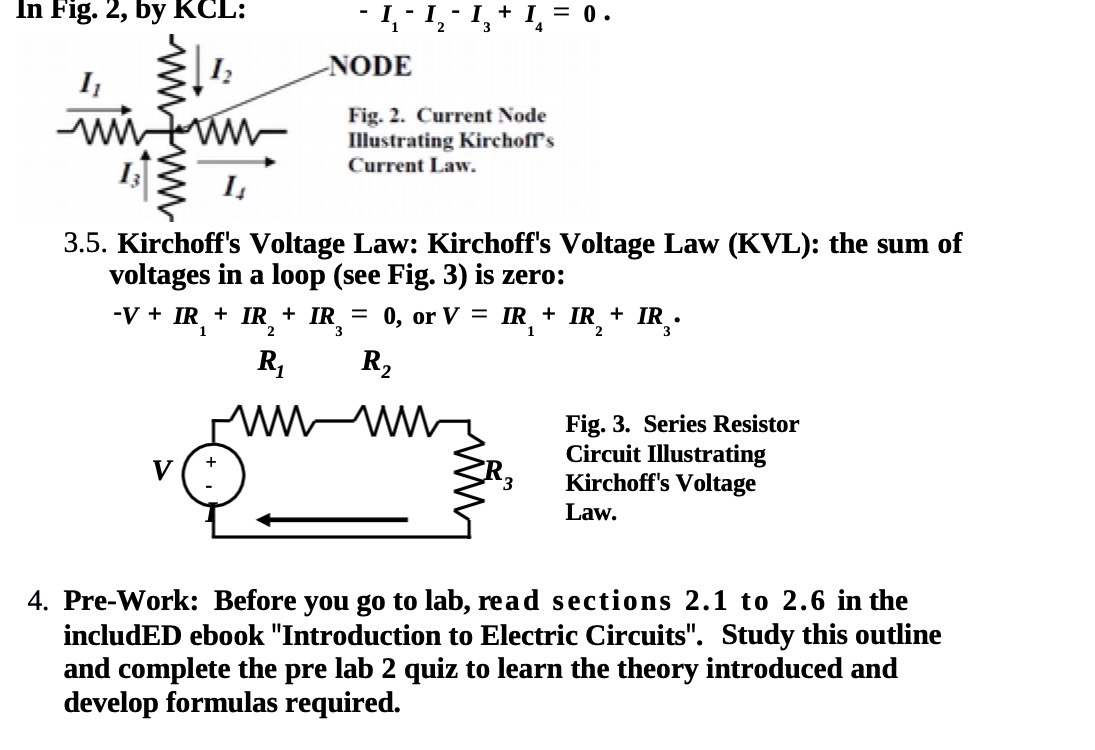
In Fig. 2, by KCL: - I -I, - I +1 =0. NODE I1 12 Fig. 2. Current Node Illustrating Kirchoff's Current Law. 3.5. Kirchoff's Voltage Law: Kirchoff's Voltage Law (KVL): the sum of voltages in a loop (see Fig. 3) is zero: -V + IR + IR + IR = 0, or V = IR + IR + IR . R2 Fig. 3. Series Resistor V Circuit Illustrating Kirchoff's Voltage Law. 4. Pre-Work: Before you go to lab, read sections 2.1 to 2.6 in the includeD ebook "Introduction to Electric Circuits". Study this outline and complete the pre lab 2 quiz to learn the theory introduced and develop formulas required
Step by Step Solution
There are 3 Steps involved in it
1 Expert Approved Answer
Step: 1 Unlock

Question Has Been Solved by an Expert!
Get step-by-step solutions from verified subject matter experts
Step: 2 Unlock
Step: 3 Unlock