

Question: in Logisim software application I NEED THE FINAL implementaion!! ( i want the final design using the software app (logic gate mux etc...) Design Requirements
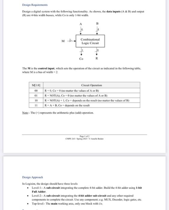
Design Requirements Desiga a digital syatem with the following functionality. As shown, the data inputs (A \& B) and output (R) are 4-bits width busses, while Ce is only I-bit width. The M is the control input, which scts the operation of the circuit as indicated in the following table. where M is a bus of width =2. Note:- The (+) represenss the arithmetic plus (add) epenation. Design Approach In Logisini, the deaign should have three levels - Level-1:- A sub-eircuit integrating the complete 4-bir adder. Build the 4-bit adder using 1-bit Fiell Adder. - Level-2:- A sub-eircuit integrating the 4-bit adder sub-circait and any other required components to complete the circuit. Use any componcat, es. MUX, Decoder, logic gates, etc. - Top-level:- The main working arca, only ene block with ilo
Step by Step Solution
There are 3 Steps involved in it

Get step-by-step solutions from verified subject matter experts