

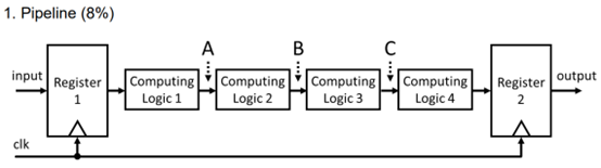
Question: In the circuit diagram above, Computing Logic 1 ~ 4 are simple combinational circuits, and Register 1 and Register 2 are both positive - edge
In the circuit diagram above, Computing Logic ~ are simple combinational circuits, and Register and Register are both positiveedgetriggered DFFs The delays of Computing Logic ~ are known to be nsnsns and ns respectively. Assume there are no other delays.
a If a pipeline register is to be added at one of the points A B or C which point is the better choice? Please explain the reason
b Considering only the delays of Computing Logic ~ and no other delays, if pipeline registers are added at points A and C what is the minimum clock cycle time that can be set without causing a timing violation? Please explain the reason
c Assuming the computation loads of Computing Logic ~ are and operations respectively, calculate the throughput for the setup described in part b
d Based on the structures described in parts a and b which configuration adding one or two pipeline registers would result in higher throughput? Please explain the reason Pipeline
Step by Step Solution
There are 3 Steps involved in it
1 Expert Approved Answer
Step: 1 Unlock

Question Has Been Solved by an Expert!
Get step-by-step solutions from verified subject matter experts
Step: 2 Unlock
Step: 3 Unlock