

Question: In the drilled shaft design example 9 - 6 , the design load is now increased to 2 0 0 tons. What will be the
In the drilled shaft design example the design load is now increased to tons. What will
be the shaft length points What is the settlement under load of tons points
In the example, beta beta is used to calculate side resistance in sand. Now, a different method is
proposed for unit side resistance in sand as follows NHI Course No
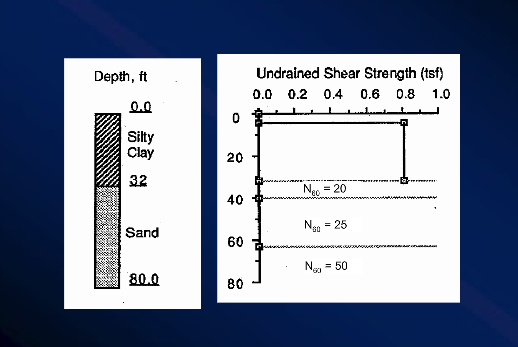
Cohesionless Soils
beta ~~sinphi sigma psigma vsinphi tanphi
Where both phi and sigma p are evaluated, most commonly, by correlation to SPT Nvalues.
sigma p effective vertical preconsolidation stress, which can be calculated as
sigma ppa~~Nm
m for silty sands, the sand in example
pa is atmospheric pressure; sigma v effective vertical overburden pressure.
You may choose a method to estimate phi from measured SPT Nvalues.
The equation below is the recommended correlation for estimating phi for the purpose of
evaluating unit side resistance of drilled shafts in cohesionless soils.
phi logN
Use alpha method for clay, and use both beta methods the one in the example and this new one
for sand. Compare the side resistance by both beta methods. The ultimate resistance of your
drilled shaft shall be no more than tons higher than the required ultimate resistance.
Please clearly explain your steps, formula, design charttable if any and references.
Step by Step Solution
There are 3 Steps involved in it
1 Expert Approved Answer
Step: 1 Unlock

Question Has Been Solved by an Expert!
Get step-by-step solutions from verified subject matter experts
Step: 2 Unlock
Step: 3 Unlock