

Question: Control system design problem Objective: Design steering angle control for an autonomous self-driving car. Statement: For this purpose, you have to design feedback based position
Control system design problem
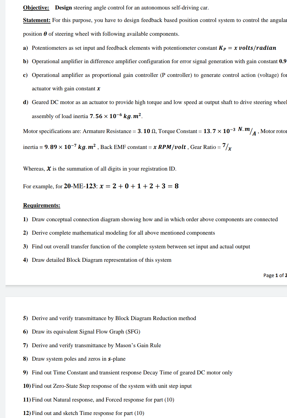
Objective: Design steering angle control for an autonomous self-driving car. Statement: For this purpose, you have to design feedback based position control system to control the angulat position of steering wheel with following available components. a) Potentiometers as set input and feedback elements with potentiometer constant KP=x volts / radian b) Operational amplifier in difference amplifier configuration for error signal generation with gain constant 0.9 c) Operational amplifier as proportional gain controller (P controller) to generate control action (voltage) for actuator with gain constant x d) Geared DC motor as an actuator to provide high torque and low speed at output shaft to drive steering wheel assembly of load inertia 7.56106kgm2. Motor specifications are: Armature Resistance =3.10, Torque Constant =13.7103N.m/A, Motor roto1 inertia =9.89107kgm2, Back EMF constant =xRPM/volt, Gear Ratio =7/x Whereas, x is the summation of all digits in your registration ID. For example, for 20-ME-123: x=2+0+1+2+3=8 Requirements: 1) Draw conceptual connection diagram showing how and in which order above components are connected 2) Derive complete mathematical modeling for all above mentioned components 3) Find out overall transfer function of the complete system between set input and actual output 4) Draw detailed Block Diagram representation of this system Page 1 of 2 5) Derive and verify transmittance by Block Diagram Reduction method 6) Draw its equivalent Signal Flow Graph (SFG) 7) Derive and verify transmittance by Mason's Gain Rule 8) Draw system poles and zeros in s-plane 9) Find out Time Constant and transient response Decay Time of geared DC motor only 10) Find out Zero-State Step response of the system with unit step input 11) Find out Natural response, and Forced response for part (10) 12) Find out and sketch Time response for part
Step by Step Solution
There are 3 Steps involved in it

Get step-by-step solutions from verified subject matter experts