

Question: In the example in given below for Virtual Circuits, give the VCI table for switch S5. As an example, consider the network below. Switch ports
In the example in given below for Virtual Circuits, give the VCI table for switch S5.
As an example, consider the network below. Switch ports are numbered 0,1,2,3. Two paths are drawn in, one from A to F in red and one from B to D in green; each link is labeled with its VCI number in the same color.
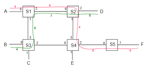
Note that either the VCIin,portin or the VCIout,portout can be used as the key; we cannot have the same pair in both the in columns and the out columns. It may help to display the port numbers for each switch, as in the upper numbers in following diagram of the above red connection from A to F (lower numbers are the VCIs):
Example of Switch S1:
| VCIin | portin | VCIout | portout | connection |
|---|---|---|---|---|
| 4 | 0 | 6 | 2 | AF #1 |
| 5 | 0 | 6 | 1 | AE |
| 6 | 0 | 7 | 1 | AC |
| 8 | 1 | 7 | 2 | BD |
| 7 | 0 | 8 | 2 | AF #2 |
Step by Step Solution
There are 3 Steps involved in it

Get step-by-step solutions from verified subject matter experts