

Question: In the figure below, the gate output voltage, Vx, takes the values 0 and +5 V when input x is logic 0 and logic
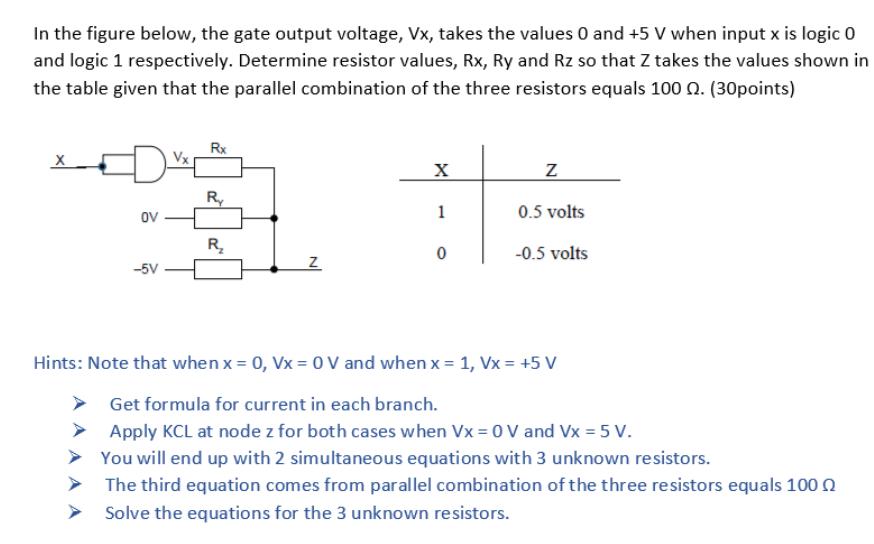
In the figure below, the gate output voltage, Vx, takes the values 0 and +5 V when input x is logic 0 and logic 1 respectively. Determine resistor values, Rx, Ry and Rz so that Z takes the values shown in the table given that the parallel combination of the three resistors equals 100 0. (30points) Rx it R ov 1 0.5 volts R, -0.5 volts -5V Hints: Note that when x 0, Vx = 0 V and when x = 1, Vx = +5 V Get formula for current in each branch. Apply KCL at node z for both cases when Vx = 0 V and Vx = 5 V. > You will end up with 2 simultaneous equations with 3 unknown resistors. > The third equation comes from parallel combination of the three resistors equals 100 0 Solve the equations for the 3 unknown resistors.
Step by Step Solution
3.48 Rating (148 Votes )
There are 3 Steps involved in it

Get step-by-step solutions from verified subject matter experts