

Question: In the past, simple CISC machines employed a bus-based architecture wherein the different components of the machine (ALU, memory, etc.) com- municated through a common
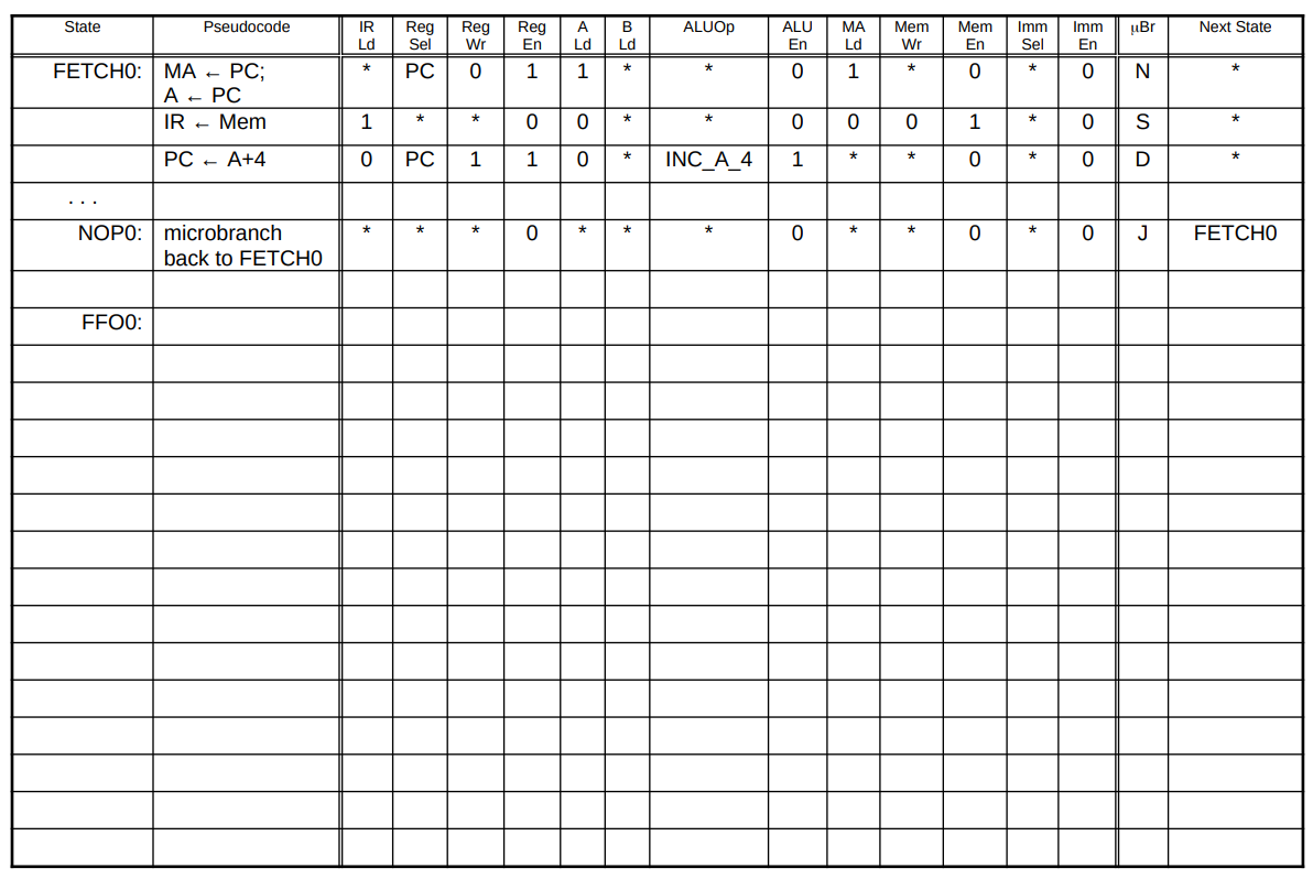
In the past, simple CISC machines employed a bus-based architecture wherein the different components of the machine (ALU, memory, etc.) com- municated through a common bus. This type of architecture is easy and inexpensive to implement but has the disadvantage of requiring all data movement between components to share the bus. Because of this bottle- neck, an instruction on such an architecture typically took several cycles to execute. Microprogramming makes it easy to generate the control signals for such multi-cycle instructions. Recall that a microcode program is basically a finite state machine de- scription where each line of microcode corresponds to a state of the machine and contains a microinstruction that specifies the outputs for that state and the next state. The outputs are used to control the different components in the datapath. The next state depends on the current state and possibly on certain other signals (e.g., condition flags). The last page shows a microcode table for the bus-based RISC-V imple- mentation. The first column in the microcode table contains the state label of each microinstruction. States are listed in increasing numerical order, and we only label important states. For example, we label state FETCHO, and assume that the unlabeled line immediately following it corresponds to state (FETCH1). The second column contains a pseudo-code explanation of the microinstruction in RTL-like notation. The rest of the columns, except the last two, represent control signals that are asserted during the current cycle. Don't care entries are marked with a "*". The last two columns specify the next state. The Br (microbranch) column represents a 3-bit field with six possible values: N, J, EZ, NZ, D and S. If Br is N (next), then the next state is simply (current state + 1). If it is J (jump), then the next state is unconditionally the state specified in the Next State column (i.e., a unconditional microbranch). If it is EZ (branch- if-equal-zero), then the next state depends on the value of the ALU zero output signal (i.e., a conditional microbranch). If zero is asserted (== 1), then the next state is that specified in the Next State column, otherwise, it is current state + 1). NZ (branch-if-not-zero) behaves exactly like EZ, except NZ branches to the next state is zero is not asserted (!= 1). If Br is D (dispatch), then the FSM looks at the opcode and function fields in the IR and goes into the corresponding state. In this handout, we assume that the dispatch goes to the state labeled (RISC-V-instruction-name + 0). For example, if the instruction in the IR is SW, then the dispatch will go to state SWO. If Br is S, then the next state depends on the value of the busy? signal. If busy? is asserted, then the next state is the same as the current state (the uPC "spins" on the same microaddress), otherwise, the next state is (current state + 1). The first three lines in the table (starting at FETCHO) form the instruc- tion fetch stage. These lines are responsible for fetching the next instruction opcode, incrementing the PC, and then jumping to the appropriate line of microcode based on the opcode fetched. The instruction fetch stage is per- formed for every instruction, and every instruction's microcode should always end by executing an instruction fetch for the next instruction. The easiest way to do this is by having the last microinstruction of an instruction's mi- crocode include a microbranch to FETCHO. The microcode for NOP provides a simple example. The 36-bit DEC PDP-10 had an instruction JFFO that would Find the First One in a register and return the number of the bit, e.g., FFO (0x1) returns 35, whereas FFO (0x800000000) would return 0. 1. Implement a FFO subroutine in RISC-V assembly language. You should return -1 if the argument is 0. Assuming each instruction takes 1 cycle, what is the average number of cycles taken by the subroutine? You should call the subroutine with the number in register A0 and the result returned in A1. The ... denotes the location of a 32 bit word. start: LW AO ... JAL FFO 2. Now, implement the FFO as an instruction using microcode. Use the table on the next page. How many microcycles on average will you need? You should assume that FFO is an ALU type instruction that just uses one source register, i.e., LW AO ... FFO A1 AO AO State Pseudocode Imm IR Ld Reg Wr ALUOP Reg Sel PC Next State B Ld MA Ld Ld 1 uBr Mem Wr Imm Sel Reg En 1 ALU En 0 Mem En 0 En 0 * * * * 0 * 1 * N FETCHO: MA MA + PC; A PC IR + Mem * * * 1 * * 0 0 00 0 1 * os * * PC PC - A+4 * 0 1 1 0 1 INC_A_4 0 * 0 D * * + * * * * 0 * la * * 0 * J FETCHO NOPO: microbranch back to FETCHO FFOO: In the past, simple CISC machines employed a bus-based architecture wherein the different components of the machine (ALU, memory, etc.) com- municated through a common bus. This type of architecture is easy and inexpensive to implement but has the disadvantage of requiring all data movement between components to share the bus. Because of this bottle- neck, an instruction on such an architecture typically took several cycles to execute. Microprogramming makes it easy to generate the control signals for such multi-cycle instructions. Recall that a microcode program is basically a finite state machine de- scription where each line of microcode corresponds to a state of the machine and contains a microinstruction that specifies the outputs for that state and the next state. The outputs are used to control the different components in the datapath. The next state depends on the current state and possibly on certain other signals (e.g., condition flags). The last page shows a microcode table for the bus-based RISC-V imple- mentation. The first column in the microcode table contains the state label of each microinstruction. States are listed in increasing numerical order, and we only label important states. For example, we label state FETCHO, and assume that the unlabeled line immediately following it corresponds to state (FETCH1). The second column contains a pseudo-code explanation of the microinstruction in RTL-like notation. The rest of the columns, except the last two, represent control signals that are asserted during the current cycle. Don't care entries are marked with a "*". The last two columns specify the next state. The Br (microbranch) column represents a 3-bit field with six possible values: N, J, EZ, NZ, D and S. If Br is N (next), then the next state is simply (current state + 1). If it is J (jump), then the next state is unconditionally the state specified in the Next State column (i.e., a unconditional microbranch). If it is EZ (branch- if-equal-zero), then the next state depends on the value of the ALU zero output signal (i.e., a conditional microbranch). If zero is asserted (== 1), then the next state is that specified in the Next State column, otherwise, it is current state + 1). NZ (branch-if-not-zero) behaves exactly like EZ, except NZ branches to the next state is zero is not asserted (!= 1). If Br is D (dispatch), then the FSM looks at the opcode and function fields in the IR and goes into the corresponding state. In this handout, we assume that the dispatch goes to the state labeled (RISC-V-instruction-name + 0). For example, if the instruction in the IR is SW, then the dispatch will go to state SWO. If Br is S, then the next state depends on the value of the busy? signal. If busy? is asserted, then the next state is the same as the current state (the uPC "spins" on the same microaddress), otherwise, the next state is (current state + 1). The first three lines in the table (starting at FETCHO) form the instruc- tion fetch stage. These lines are responsible for fetching the next instruction opcode, incrementing the PC, and then jumping to the appropriate line of microcode based on the opcode fetched. The instruction fetch stage is per- formed for every instruction, and every instruction's microcode should always end by executing an instruction fetch for the next instruction. The easiest way to do this is by having the last microinstruction of an instruction's mi- crocode include a microbranch to FETCHO. The microcode for NOP provides a simple example. The 36-bit DEC PDP-10 had an instruction JFFO that would Find the First One in a register and return the number of the bit, e.g., FFO (0x1) returns 35, whereas FFO (0x800000000) would return 0. 1. Implement a FFO subroutine in RISC-V assembly language. You should return -1 if the argument is 0. Assuming each instruction takes 1 cycle, what is the average number of cycles taken by the subroutine? You should call the subroutine with the number in register A0 and the result returned in A1. The ... denotes the location of a 32 bit word. start: LW AO ... JAL FFO 2. Now, implement the FFO as an instruction using microcode. Use the table on the next page. How many microcycles on average will you need? You should assume that FFO is an ALU type instruction that just uses one source register, i.e., LW AO ... FFO A1 AO AO State Pseudocode Imm IR Ld Reg Wr ALUOP Reg Sel PC Next State B Ld MA Ld Ld 1 uBr Mem Wr Imm Sel Reg En 1 ALU En 0 Mem En 0 En 0 * * * * 0 * 1 * N FETCHO: MA MA + PC; A PC IR + Mem * * * 1 * * 0 0 00 0 1 * os * * PC PC - A+4 * 0 1 1 0 1 INC_A_4 0 * 0 D * * + * * * * 0 * la * * 0 * J FETCHO NOPO: microbranch back to FETCHO FFOO
Step by Step Solution
There are 3 Steps involved in it

Get step-by-step solutions from verified subject matter experts