

In the previous few labs, we have learned the transformation matrices of robotic system in two-...
Fantastic news! We've Found the answer you've been seeking!
Question:
Transcribed Image Text:
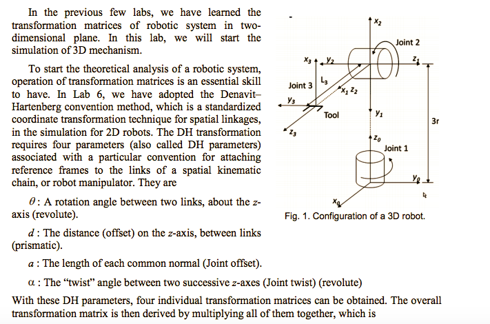
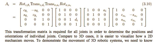
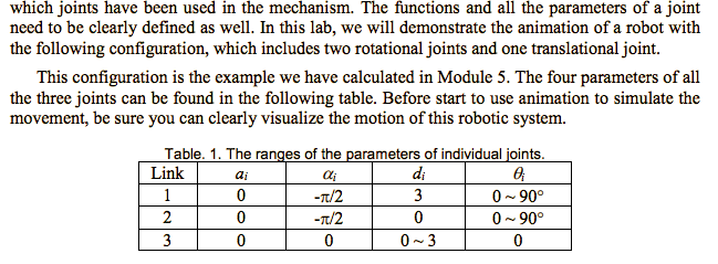
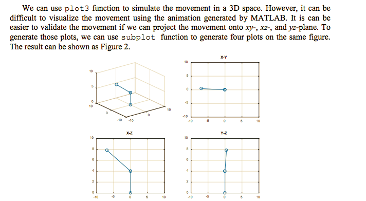
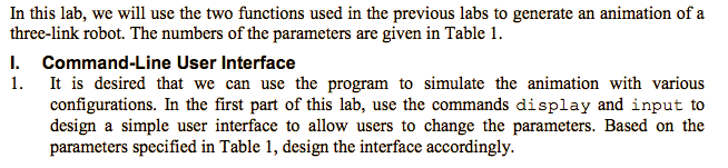
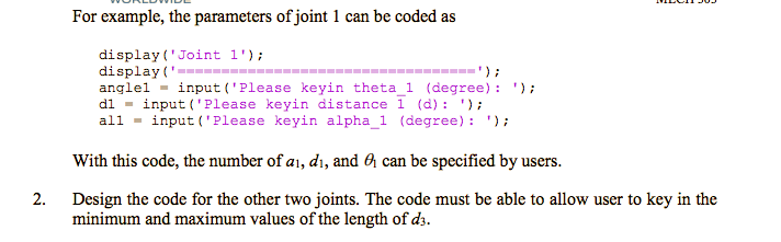
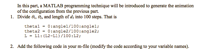
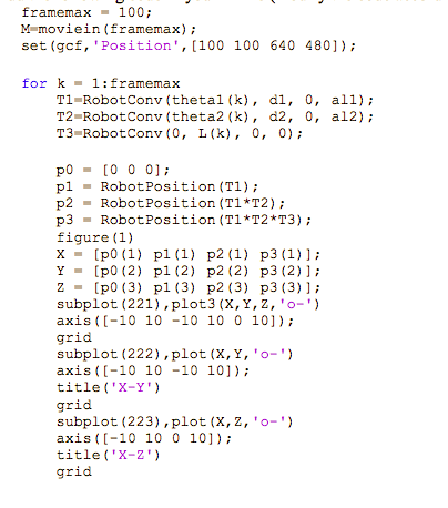
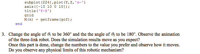
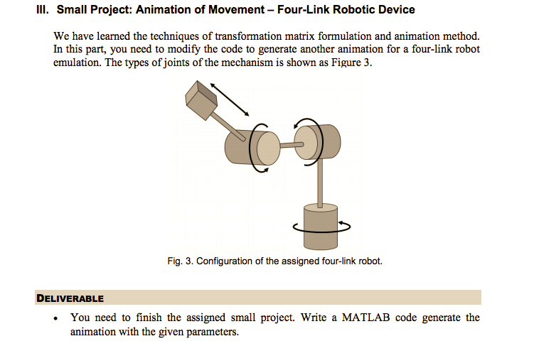
In the previous few labs, we have learned the transformation matrices of robotic system in two- dimensional plane. In this lab, we will start the simulation of 3D mechanism. To start the theoretical analysis of a robotic system, operation of transformation matrices is an essential skill to have. In Lab 6, we have adopted the Denavit- Hartenberg convention method, which is a standardized coordinate transformation technique for spatial linkages, in the simulation for 2D robots. The DH transformation requires four parameters (also called DH parameters) associated with a particular convention for attaching reference frames to the links of a spatial kinematic chain, or robot manipulator. They are 0: A rotation angle between two links, about the z- axis (revolute). d: The distance (offset) on the z-axis, between links (prismatic). a: The length of each common normal (Joint offset). X3+Y2 L3 Joint 3 Y3 Tool Zo Joint 2 Joint 1 Fig. 1. Configuration of a 3D robot. 3r a: The "twist" angle between two successive z-axes (Joint twist) (revolute) With these DH parameters, four individual transformation matrices can be obtained. The overall transformation matrix is then derived by multiplying all of them together, which is A = Rotze, Transz,d, Transa,a, Rotx, ][ . 50, 0 00 -80, co, 0 10 00 0 0 01 100 aj 1000 0100 0100 ][ 001 di 0010 0001 0001 1 ||| 0 000 -Sai Cai 0 Cai (3.10) 0 Sai 0 0 0 0 1 This transformation matrix is required for all joints in order to determine the positions and orientations of individual joints. Compare to 3D cases, it is easier to visualize how a 2D mechanism moves. To demonstrate the movement of 3D robotic systems, we need to know which joints have been used in the mechanism. The functions and all the parameters of a joint need to be clearly defined as well. In this lab, we will demonstrate the animation of a robot with the following configuration, which includes two rotational joints and one translational joint. This configuration is the example we have calculated in Module 5. The four parameters of all the three joints can be found in the following table. Before start to use animation to simulate the movement, be sure you can clearly visualize the motion of this robotic system. Table. 1. The ranges of the parameters of individual joints. Link ai Oli di 0; 1 0 -/2 3 0~90 2 0 -/2 0 0~90 3 0 0 0~3 0 We can use plot 3 function to simulate the movement in a 3D space. However, it can be difficult to visualize the movement using the animation generated by MATLAB. It is can be easier to validate the movement if we can project the movement onto xy-, xz-, and yz-plane. To generate those plots, we can use subplot function to generate four plots on the same figure. The result can be shown as Figure 2. 10 5 0 10 10 8 6 4 2 0 0 -10 -10 X-Z 0 0 10 10 10 5 0 -5 -10 10 -10 8 4 2 0 -10 G -5 -5 0 Y-Z 0 5 10 10 In this lab, we will use the two functions used in the previous labs to generate an animation of a three-link robot. The numbers of the parameters are given in Table 1. I. Command-Line User Interface 1. It is desired that we can use the program to simulate the animation with various configurations. In the first part of this lab, use the commands display and input to design a simple user interface to allow users to change the parameters. Based on the parameters specified in Table 1, design the interface accordingly. 2. For example, the parameters of joint 1 can be coded as display('Joint 1'); display ( anglel input ('Please keyin theta_1 (degree) : dl input ('Please keyin distance 1 (d) : '); all input ('Please keyin alpha_1 (degree) : '); With this code, the number of ai, di, and can be specified by users. Design the code for the other two joints. The code must be able to allow user to key in the minimum and maximum values of the length of d3. In this part, a MATLAB programming technique will be introduced to generate the animation of the configuration from the previous part. 1. Divide 1, 2, and length of d3 into 100 steps. That is thetal = 0: anglel/100: anglel; theta2 = 0: angle2/100: angle2; L = L1: (L2-L1)/100:12; 2. Add the following code in your m-file (modify the code according to your variable names). framemax = 100; M moviein (framemax); set (gcf, 'Position', [100 100 640 480]); for k=1: framemax T1-RobotConv (thetal (k), dl, 0, all); T2 RobotConv (theta2 (k), d2, 0, al2); T3-RobotConv (0, L (k), 0, 0); po pl p2 - RobotPosition (T1*T2); p3 Robot Position (T1*T2*T3); figure (1) PR X Y Z pl (1) p2 (1) p3 (1)]; p1 (2) p2 (2) p3 (2)]; p1 (3) p2 (3) p3 (3)]; subplot (221), plot3 (X, Y, Z, '0-) axis ([-10 10 -10 10 0 10]); grid [0 0 0]; Robot Position (T1); [p0 (1) [p0 (2) [p0 (3) grid subplot (222), plot (X, Y, 'o-') axis ([-10 10 -10 10]); title ('X-Y') grid subplot (223), plot (X,Z, 'o-') axis ([-10 10 0 10]); title('X-Z') end subplot (224), plot (Y, Z, 'o-') axis ([-10 10 0 10]); title('Y-Z') grid M (k) getframe (gcf); 3. Change the angle of to be 360 and the the angle of 2 to be 180. Observe the animation of the three-link robot. Does the simulation results move as you expect? Once this part is done, change the numbers to the value you prefer and observe how it moves. Do you observe any physical limits of this robotic mechanism? III. Small Project: Animation of Movement - Four-Link Robotic Device We have learned the techniques of transformation matrix formulation and animation method. In this part, you need to modify the code to generate another animation for a four-link robot emulation. The types of joints of the mechanism is shown as Figure 3. Fig. 3. Configuration of the assigned four-link robot. DELIVERABLE You need to finish the assigned small project. Write a MATLAB code generate the animation with the given parameters. In the previous few labs, we have learned the transformation matrices of robotic system in two- dimensional plane. In this lab, we will start the simulation of 3D mechanism. To start the theoretical analysis of a robotic system, operation of transformation matrices is an essential skill to have. In Lab 6, we have adopted the Denavit- Hartenberg convention method, which is a standardized coordinate transformation technique for spatial linkages, in the simulation for 2D robots. The DH transformation requires four parameters (also called DH parameters) associated with a particular convention for attaching reference frames to the links of a spatial kinematic chain, or robot manipulator. They are 0: A rotation angle between two links, about the z- axis (revolute). d: The distance (offset) on the z-axis, between links (prismatic). a: The length of each common normal (Joint offset). X3+Y2 L3 Joint 3 Y3 Tool Zo Joint 2 Joint 1 Fig. 1. Configuration of a 3D robot. 3r a: The "twist" angle between two successive z-axes (Joint twist) (revolute) With these DH parameters, four individual transformation matrices can be obtained. The overall transformation matrix is then derived by multiplying all of them together, which is A = Rotze, Transz,d, Transa,a, Rotx, ][ . 50, 0 00 -80, co, 0 10 00 0 0 01 100 aj 1000 0100 0100 ][ 001 di 0010 0001 0001 1 ||| 0 000 -Sai Cai 0 Cai (3.10) 0 Sai 0 0 0 0 1 This transformation matrix is required for all joints in order to determine the positions and orientations of individual joints. Compare to 3D cases, it is easier to visualize how a 2D mechanism moves. To demonstrate the movement of 3D robotic systems, we need to know which joints have been used in the mechanism. The functions and all the parameters of a joint need to be clearly defined as well. In this lab, we will demonstrate the animation of a robot with the following configuration, which includes two rotational joints and one translational joint. This configuration is the example we have calculated in Module 5. The four parameters of all the three joints can be found in the following table. Before start to use animation to simulate the movement, be sure you can clearly visualize the motion of this robotic system. Table. 1. The ranges of the parameters of individual joints. Link ai Oli di 0; 1 0 -/2 3 0~90 2 0 -/2 0 0~90 3 0 0 0~3 0 We can use plot 3 function to simulate the movement in a 3D space. However, it can be difficult to visualize the movement using the animation generated by MATLAB. It is can be easier to validate the movement if we can project the movement onto xy-, xz-, and yz-plane. To generate those plots, we can use subplot function to generate four plots on the same figure. The result can be shown as Figure 2. 10 5 0 10 10 8 6 4 2 0 0 -10 -10 X-Z 0 0 10 10 10 5 0 -5 -10 10 -10 8 4 2 0 -10 G -5 -5 0 Y-Z 0 5 10 10 In this lab, we will use the two functions used in the previous labs to generate an animation of a three-link robot. The numbers of the parameters are given in Table 1. I. Command-Line User Interface 1. It is desired that we can use the program to simulate the animation with various configurations. In the first part of this lab, use the commands display and input to design a simple user interface to allow users to change the parameters. Based on the parameters specified in Table 1, design the interface accordingly. 2. For example, the parameters of joint 1 can be coded as display('Joint 1'); display ( anglel input ('Please keyin theta_1 (degree) : dl input ('Please keyin distance 1 (d) : '); all input ('Please keyin alpha_1 (degree) : '); With this code, the number of ai, di, and can be specified by users. Design the code for the other two joints. The code must be able to allow user to key in the minimum and maximum values of the length of d3. In this part, a MATLAB programming technique will be introduced to generate the animation of the configuration from the previous part. 1. Divide 1, 2, and length of d3 into 100 steps. That is thetal = 0: anglel/100: anglel; theta2 = 0: angle2/100: angle2; L = L1: (L2-L1)/100:12; 2. Add the following code in your m-file (modify the code according to your variable names). framemax = 100; M moviein (framemax); set (gcf, 'Position', [100 100 640 480]); for k=1: framemax T1-RobotConv (thetal (k), dl, 0, all); T2 RobotConv (theta2 (k), d2, 0, al2); T3-RobotConv (0, L (k), 0, 0); po pl p2 - RobotPosition (T1*T2); p3 Robot Position (T1*T2*T3); figure (1) PR X Y Z pl (1) p2 (1) p3 (1)]; p1 (2) p2 (2) p3 (2)]; p1 (3) p2 (3) p3 (3)]; subplot (221), plot3 (X, Y, Z, '0-) axis ([-10 10 -10 10 0 10]); grid [0 0 0]; Robot Position (T1); [p0 (1) [p0 (2) [p0 (3) grid subplot (222), plot (X, Y, 'o-') axis ([-10 10 -10 10]); title ('X-Y') grid subplot (223), plot (X,Z, 'o-') axis ([-10 10 0 10]); title('X-Z') end subplot (224), plot (Y, Z, 'o-') axis ([-10 10 0 10]); title('Y-Z') grid M (k) getframe (gcf); 3. Change the angle of to be 360 and the the angle of 2 to be 180. Observe the animation of the three-link robot. Does the simulation results move as you expect? Once this part is done, change the numbers to the value you prefer and observe how it moves. Do you observe any physical limits of this robotic mechanism? III. Small Project: Animation of Movement - Four-Link Robotic Device We have learned the techniques of transformation matrix formulation and animation method. In this part, you need to modify the code to generate another animation for a four-link robot emulation. The types of joints of the mechanism is shown as Figure 3. Fig. 3. Configuration of the assigned four-link robot. DELIVERABLE You need to finish the assigned small project. Write a MATLAB code generate the animation with the given parameters.
Expert Answer:

Related Book For 

Posted Date:
Students also viewed these databases questions
-
QUIZ... Let D be a poset and let f : D D be a monotone function. (i) Give the definition of the least pre-fixed point, fix (f), of f. Show that fix (f) is a fixed point of f. [5 marks] (ii) Show that...
-
Ethanol reacts with sodium and forms two products which are Options: 1) Sodium ethanoate and hydrogen 2) Sodium ethanoate and oxygen 3) Sodium ethoxide and hydrogen 4) Sodium ethoxide and oxygen
-
Stock is often considered the riskiest type of investment vehicle. The reasoning behind the risky label is the fact that company stock prices can move up or down rapidly, and many internal and...
-
Describe the following requirements that help to achieve audit quality and thereby help to minimize the exposure of external auditors to lawsuits: a. Maintaining auditor independence b. Participating...
-
If among \(n\) objects \(k\) are alike and the others are all distinct, the number of permutations of these \(n\) objects taken all together is \(n ! / k !\). (a) How many permutations are there of...
-
How might a company configure its strategy-making processes to reduce the probability that managers will pursue their own self-interest, at the expense of stockholders?
-
Describe the physical principles that explain electric motors and generators and the conceptual similarities between these devices. Showing your thoughts by drawing pictures.
-
Write a query to create primary constraints with table level with naming convention.
-
Catherine has worked for a company in Edmonton, Alberta since 2 0 1 2 . She earns $ 3 7 . 3 5 per hour, works 4 0 hours per pay period and is paid on a weekly basis. The company provides its...
-
curl F div F is F conservative (Y/N)? Fill in the following table. (Enter vectors in the form < a, b, c >) F xyzi + 8j+xyk 7ei 14ej+7ek
-
Night Shades, Incorporated, manufactures biotech sunglasses. The variable materials cost is $ 1 2 . 2 0 per unit, and the variable labor cost is $ 6 . 0 0 per unit. a . What is the variable cost per...
-
For companies that manufacture several products that use different proportions of manufacturing overhead resources, why does the use of activity-based costing provide more reliable product cost...
-
Cortez Company sells chairs that are used at computer stations. Its beginning inventory of chairs was 2 2 0 units at $ 4 9 per unit. During the year, Cortez made two batch purchases of this chair....
-
. Prepare a trial balance, multi-step income statement, statement of retained earnings, and balance sheet for Porter Company as of December 31, 2021 All statements should be completed in the "Porter...
-
What are the four types of poultry production systems? Explain each type.
-
Predict the products that are expected when each of the following alkenes is treated with ozone followed by DMS: a. b. c. d. e. f.
-
The C-H bonds shown in red exhibit very similar BDEs, because homolytic cleavage of either bond results in a resonance-stabilized radical. Nevertheless, one of these C-H bonds is weaker than the...
-
Propose a mechanism for each of the following transformations: a. b.
-
Many states have lotteries that involve the random selection of digits 0, 1, 2, ,
-
Is the distribution of those digits a normal distribution? Why or why not?
-
Birth weights in the United States are normally distributed with a mean (in grams) of 3420 g and a standard deviation of 495 g. If you graph this normal distribution, the area to the right of 4000 g...

Study smarter with the SolutionInn App