

In this project you are going to design a traffic-light controller for the street intersection shown...
Fantastic news! We've Found the answer you've been seeking!
Question:
Transcribed Image Text:
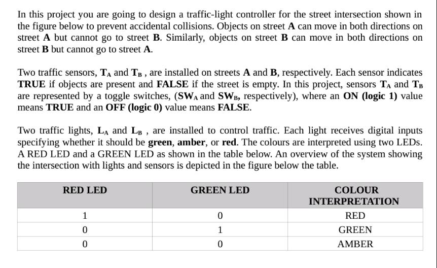
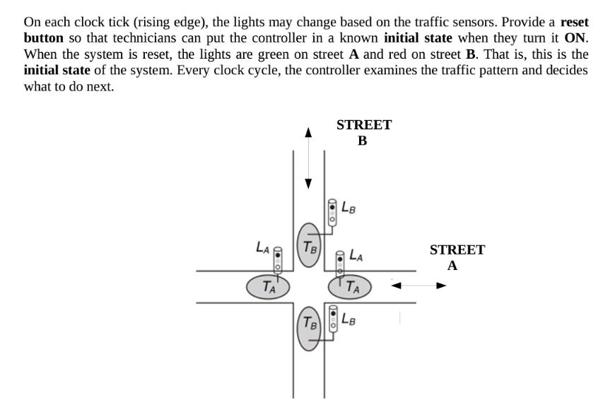
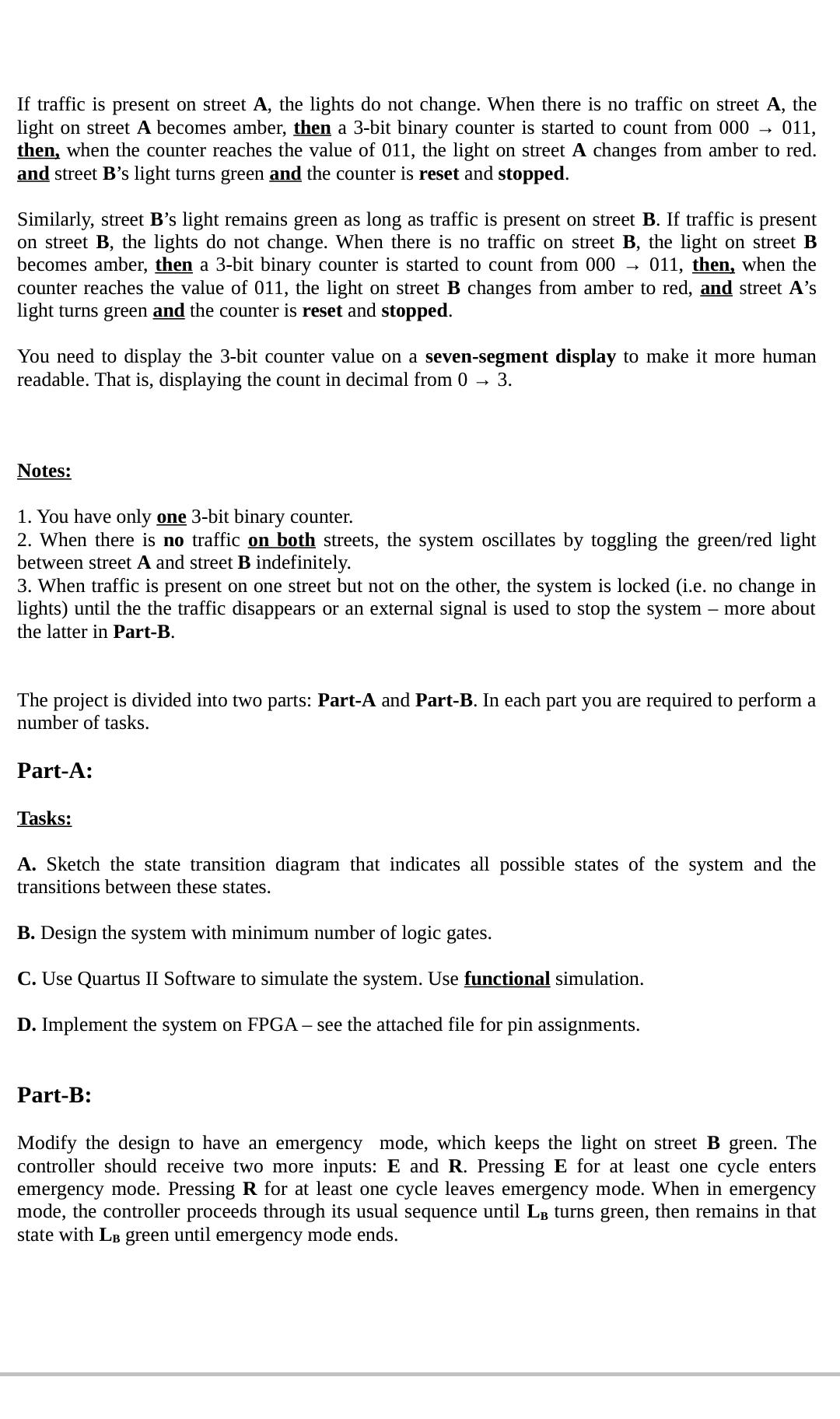
In this project you are going to design a traffic-light controller for the street intersection shown in the figure below to prevent accidental collisions. Objects on street A can move in both directions on street A but cannot go to street B. Similarly, objects on street B can move in both directions on street B but cannot go to street A. Two traffic sensors, T₁ and TB, are installed on streets A and B, respectively. Each sensor indicates TRUE if objects are present and FALSE if the street is empty. In this project, sensors T₁ and TB are represented by a toggle switches, (SWA and SWB, respectively), where an ON (logic 1) value means TRUE and an OFF (logic 0) value means FALSE. Two traffic lights, LA and LB, are installed to control traffic. Each light receives digital inputs specifying whether it should be green, amber, or red. The colours are interpreted using two LEDs. A RED LED and a GREEN LED as shown in the table below. An overview of the system showing the intersection with lights and sensors is depicted in the figure below the table. RED LED 1 0 0 GREEN LED 0 1 0 COLOUR INTERPRETATION RED GREEN AMBER On each clock tick (rising edge), the lights may change based on the traffic sensors. Provide a reset button so that technicians can put the controller in a known initial state when they turn it ON. When the system is reset, the lights are green on street A and red on street B. That is, this is the initial state of the system. Every clock cycle, the controller examines the traffic pattern and decides what to do next. LA 1.0 ΤΑ TB Тв STREET B LB LA TA LB STREET A If traffic is present on street A, the lights do not change. When there is no traffic on street A, the light on street A becomes amber, then a 3-bit binary counter is started to count from 000 011, then, when the counter reaches the value of 011, the light on street A changes from amber to red. and street B's light turns green and the counter is reset and stopped. Similarly, street B's light remains green as long as traffic is present on street B. If traffic is present on street B, the lights do not change. When there is no traffic on street B, the light on street B becomes amber, then a 3-bit binary counter is started to count from 000 → 011, then, when the counter reaches the value of 011, the light on street B changes from amber to red, and street A's light turns green and the counter is reset and stopped. You need to display the 3-bit counter value on a seven-segment display to make it more human readable. That is, displaying the count in decimal from 0 3. Notes: 1. You have only one 3-bit binary counter. 2. When there is no traffic on both streets, the system oscillates by toggling the green/red light between street A and street B indefinitely. 3. When traffic is present on one street but not on the other, the system is locked (i.e. no change in lights) until the the traffic disappears or an external signal is used to stop the system - more about the latter in Part-B. The project is divided into two parts: Part-A and Part-B. In each part you are required to perform a number of tasks. Part-A: Tasks: A. Sketch the state transition diagram that indicates all possible states of the system and the transitions between these states. B. Design the system with minimum number of logic gates. C. Use Quartus II Software to simulate the system. Use functional simulation. D. Implement the system on FPGA - see the attached file for pin assignments. Part-B: Modify the design to have an emergency mode, which keeps the light on street B green. The controller should receive two more inputs: E and R. Pressing E for at least one cycle enters emergency mode. Pressing R for at least one cycle leaves emergency mode. When in emergency mode, the controller proceeds through its usual sequence until LB turns green, then remains in that state with LB green until emergency mode ends. Tasks: A. Sketch the state transition diagram that indicates all possible states of the system and the transitions between these states. B. Design the system with minimum number of logic gates. C. Use Quartus II Software to simulate the system. Use functional simulation. In this project you are going to design a traffic-light controller for the street intersection shown in the figure below to prevent accidental collisions. Objects on street A can move in both directions on street A but cannot go to street B. Similarly, objects on street B can move in both directions on street B but cannot go to street A. Two traffic sensors, T₁ and TB, are installed on streets A and B, respectively. Each sensor indicates TRUE if objects are present and FALSE if the street is empty. In this project, sensors T₁ and TB are represented by a toggle switches, (SWA and SWB, respectively), where an ON (logic 1) value means TRUE and an OFF (logic 0) value means FALSE. Two traffic lights, LA and LB, are installed to control traffic. Each light receives digital inputs specifying whether it should be green, amber, or red. The colours are interpreted using two LEDs. A RED LED and a GREEN LED as shown in the table below. An overview of the system showing the intersection with lights and sensors is depicted in the figure below the table. RED LED 1 0 0 GREEN LED 0 1 0 COLOUR INTERPRETATION RED GREEN AMBER On each clock tick (rising edge), the lights may change based on the traffic sensors. Provide a reset button so that technicians can put the controller in a known initial state when they turn it ON. When the system is reset, the lights are green on street A and red on street B. That is, this is the initial state of the system. Every clock cycle, the controller examines the traffic pattern and decides what to do next. LA 1.0 ΤΑ TB Тв STREET B LB LA TA LB STREET A If traffic is present on street A, the lights do not change. When there is no traffic on street A, the light on street A becomes amber, then a 3-bit binary counter is started to count from 000 011, then, when the counter reaches the value of 011, the light on street A changes from amber to red. and street B's light turns green and the counter is reset and stopped. Similarly, street B's light remains green as long as traffic is present on street B. If traffic is present on street B, the lights do not change. When there is no traffic on street B, the light on street B becomes amber, then a 3-bit binary counter is started to count from 000 → 011, then, when the counter reaches the value of 011, the light on street B changes from amber to red, and street A's light turns green and the counter is reset and stopped. You need to display the 3-bit counter value on a seven-segment display to make it more human readable. That is, displaying the count in decimal from 0 3. Notes: 1. You have only one 3-bit binary counter. 2. When there is no traffic on both streets, the system oscillates by toggling the green/red light between street A and street B indefinitely. 3. When traffic is present on one street but not on the other, the system is locked (i.e. no change in lights) until the the traffic disappears or an external signal is used to stop the system - more about the latter in Part-B. The project is divided into two parts: Part-A and Part-B. In each part you are required to perform a number of tasks. Part-A: Tasks: A. Sketch the state transition diagram that indicates all possible states of the system and the transitions between these states. B. Design the system with minimum number of logic gates. C. Use Quartus II Software to simulate the system. Use functional simulation. D. Implement the system on FPGA - see the attached file for pin assignments. Part-B: Modify the design to have an emergency mode, which keeps the light on street B green. The controller should receive two more inputs: E and R. Pressing E for at least one cycle enters emergency mode. Pressing R for at least one cycle leaves emergency mode. When in emergency mode, the controller proceeds through its usual sequence until LB turns green, then remains in that state with LB green until emergency mode ends. Tasks: A. Sketch the state transition diagram that indicates all possible states of the system and the transitions between these states. B. Design the system with minimum number of logic gates. C. Use Quartus II Software to simulate the system. Use functional simulation.
Expert Answer:
Answer rating: 100% (QA)
Here is my approach to solving this multipart traffic light controller design problem Part A ... View the full answer

Related Book For 

Principles of Information Systems
ISBN: 978-1133629665
11th edition
Authors: Ralph Stair, George Reynolds
Posted Date:
Students also viewed these accounting questions
-
An ideal monoatomic gas is confined in a horizontal cylinder by a spring loaded piston (as shown in the figure). Initially the gas is at temperature T, pressure P and volume V, and the spring is in...
-
In August 2014, Jim acquired a 99-year lease on a flat for 170,000. In August 2020, he assigned the lease to Shirley for 212,000. The flat was never Jim's residence. Compute the chargeable gain.
-
Refer to the information for Toby's on the previous page. Last year, Toby's Hats had net sales of $45,000,000 and cost of goods sold of $29,000,000. Toby's had the following balances:...
-
Interview a friend employed in your career field or interview a benefits representative from a company agency in your career field. Discuss the benefits that you might expect to receive as an...
-
Distinguish same-sex marriage from other forms of marriage in its effect.
-
How does an organization know if it is pursuing optimal strategies?
-
Suppose that the supply curve of serving in the military is S(P) = P, where Q = S(P) is several hours employed in military service a day. There are only mercenaries in the army (there is no draft). P...
-
Restaurants offer a variety of menu items which have different sizes, ingredients, packaging, and demand. In addition, made-to-order restaurants go one step further and may have different renditions...
-
What Is Training? What Are The Objectives Of Training Department?
-
A TIME TO KILL FILM Reflection Questions: Summative assignment (1) Create a flow chart of a criminal court case based on the events in this film. At each juncture, provide a brief summary for the...
-
For the past year, A firm has sales of $46,772, interest expense of $4,010, cost of goods sold of $17,009, selling and administrative expense of $11,956, and depreciation of $6,705. If the tax rate...
-
Determine theoretical. According to the theory, for light refracting from water into air, the critical angle will Occur at an incident angle Oc where n sin(0)= sin(90). Using your experimental value...
-
A person is holding two drill bits: one is 3/8 and one is 11/32. The person wants to first drill a hole using the smaller of the two bits. To decide which is smaller, the person expands 3/8 to 32nds....
-
Complete the following synthesis. Draw the mechanism for every step. Complete the following syntheses. You do NOT need to show the mechanism 1. H2N Novocaine 2. . 3.
-
If the amplifier indicated by the box input impedance of oo, which of the following statements are true ? has an open loop gain as well as Feedback factor (\beta = 1/ R_1\) The feedback is voltage...
-
What are the stages of problem solving?
-
What is the difference between freeware and open-source software?
-
What types of services will be provided over Altitude Onlines network?
-
An engine runs on a rich mixture of methyl and ethyl alcohol and air. At a pressure of 1 bar and \(10^{\circ} \mathrm{C}\) the fuel is completely vapourised. Calculate the air-fuel ratio by volume...
-
A closed vessel of \(0.15 \mathrm{~m}^{3}\) capacity contains a mixture of methane \(\left(\mathrm{CH}_{4} ight)\) and air, the air being \(20 \%\) in excess of that required for chemically correct...
-
Show, for a gas obeying the state equation \[p v=(1+\alpha) \Re T\] where \(\alpha\) is a function of temperature alone, that the specific heat at constant pressure is given by \[c_{p}=-\Re T...

Study smarter with the SolutionInn App