

Question: In this project you will build a traffic light controller using only registers ( D - flip flops ) and basic logic gates ( AND
In this project you will build a traffic light controller using only registers Dflip flops and basic logic gates AND OR NAND, NOR, NOT
The Problem
You are modeling the lights for a small northsouth road making a T junction with a larger eastwest road. For example, let's take the Summer St and Plymouth St intersection on campus:
There are two sets of lights: Red, Yellow, Green for the EastWestbound traffic, and Red, Yellow, Green for the northbound traffic. The light normally stays green for the EastWest street unless a northbound car activates a switch. Let's say, for simplicity, that red lights last for seconds, green for seconds, yellow for second.
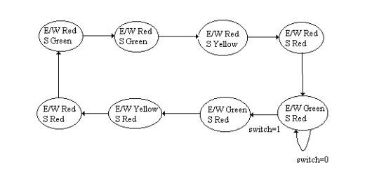
The state diagram for this problem looks like this:
Objective
Your objective is to design and construct a digital circuit to control these traffic lights. Your circuit will have one input is a northbound car waiting and six outputs: onoff for each light on the two traffic signals. You should design a circuit in the Emumaker simulator provided on Blackboard. For full credit, you should implement this circuit using an Arduino Uno and a breadboard.
Step : Truth Table
Design a transition truth table for this traffic light controller. Your table should have inputs switch, bit current state and outputs bit next state, lights
Step : Equations
Make the full SumofProducts logic equations. There should be nine of them.
Step optional but strongly encouraged: Simplify
Simplify the equations as much as you can.
Step : Build it
Build the circuit in the simulator. Use an inputpin for the car switch and six output pins for the lights. You may use either bit registers or NAND gates as Dflipflops to store your state. The rest of your circuit must consist only of ANDORNANDNORNOT gates and buses.
Step : Test it
If you used a register for storage you should press Simulate, and press the STEP button once per second to cycle through the lights. If you chose to make your flipflops out of registers, you will have an addition "Clock" inputpin that you will click to advance to the next state.
Submit your simulator save file to Blackboard.
Step : Get the breadboard ready
Set up six LEDs green, yellow, red and make sure that they are connected through a k brownblackred resistor to ground. If you are completing this at home, you will need to construct the oscillator circuit from Lab to drive the Clock input pin. Alternatively, if you can make it to school, then use the TTL clock output on one of the blue lab boards.
Step : Install the software
Download the Arduino IDE from the web, install it Press the Export button and save your work to trafficlight.ino. Open it in the Arduino IDE. Upload it to an Uno.
Step : Connect your Uno to the circuit
Look in the comments at the top of trafficlight.ino to see which pins correspond to which input and output pins in your circuit. Then connect the LEDs and the Clk or switch to the appropriate holes. Make sure that you connect GND on the breadboard to GND on the Uno. Does it work?
Step by Step Solution
There are 3 Steps involved in it
1 Expert Approved Answer
Step: 1 Unlock

Question Has Been Solved by an Expert!
Get step-by-step solutions from verified subject matter experts
Step: 2 Unlock
Step: 3 Unlock