

Question: This is the 555 timer This is the 74163 binary counter This is the 74138 decoder Design and build a traffic light circuit that makes
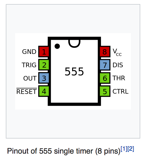
This is the 555 timer
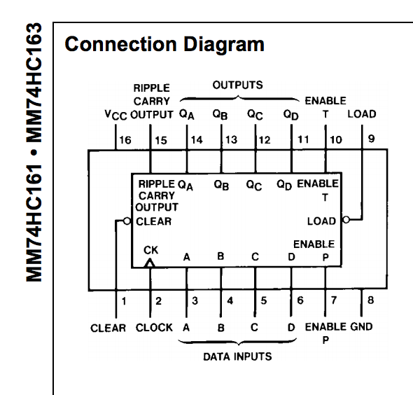
This is the 74163 binary counter
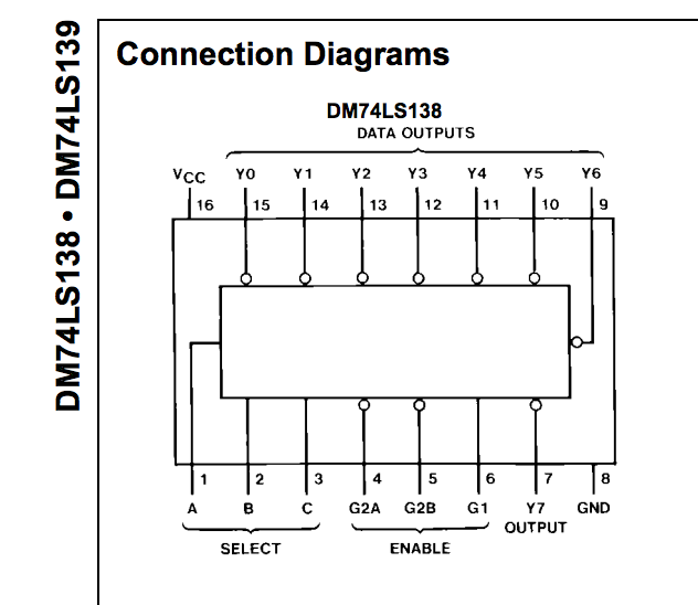
This is the 74138 decoder
Design and build a traffic light circuit that makes use of the micro-computational capability of the 555/74163/74138 three-chip controller circuit.
Traffic lights continuously cycle the illumination of three different colored lights: green, yellow, and red. Use green, RGB, and red LEDs to create the green, yellow, and red output. Use the RGB LED to display yellow light (roughly) by turning on both the red and green emitters. The output of your traffic signal must show green for 4 seconds, followed by yellow for 1 second, followed by red for 3 seconds, and then repeat in this order.
Design three combinatorial circuits, one to compute the signal for each traffic light color. The controller circuit provides eight outputs from the demultiplexer and three outputs from the counter. Any of these outputs may be helpful in developing the signals for the traffic light. You may also use NAND and NOR gates to implement your computational logic, as you see fit.
Create a truth table for each color of the traffic light. Use outputs from either the counter or decoder as inputs for the truth tables. Think about the operation of a traffic light and think about which of the counter or decoder outputs are similar in timing and logic level to the signal you need for a given traffic light. Using an existing signal that is similar to the LED signal needed for a given light means a simpler computation to perform to create the actual LED signal and, thus, a simpler combinatorial circuit to build.
For your traffic light design, write the Boolean expression for each traffic light color, and simplify to 2-input NAND and/or NOR gates.
Draw the schematic diagram of your traffic light circuits, following the expression you just derived
GND 8 1 TRIG 2 OUT 3 RESET 4 ouT3555DIS 6 THR 5 CTRL Pinout of 555 single timer (8 pins) 12] [1112 GND 8 1 TRIG 2 OUT 3 RESET 4 ouT3555DIS 6 THR 5 CTRL Pinout of 555 single timer (8 pins) 12] [1112
Step by Step Solution
There are 3 Steps involved in it

Get step-by-step solutions from verified subject matter experts