

Question: In this task you will program the PLD with the digital circuit shown below: Figure 2: Logie diagram of Boolean function You are required to
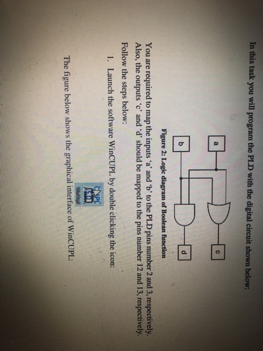
In this task you will program the PLD with the digital circuit shown below: Figure 2: Logie diagram of Boolean function You are required to map the inputs 'a' and 'b' to the PLD pins number 2 and 3, respectively. Also, the outputs 'c' and 'd' should be mapped to the pins number 12 and 13, respectively Follow the steps below: 1. Launch the software WinCUPL by double clicking the icon: The figure below shows the graphical interface of WinCUPL
Step by Step Solution
There are 3 Steps involved in it
1 Expert Approved Answer
Step: 1 Unlock

Question Has Been Solved by an Expert!
Get step-by-step solutions from verified subject matter experts
Step: 2 Unlock
Step: 3 Unlock