

Question: Introduction: You have been asked to undertake a structural analysis on a concept design for a low cost stroller / buggy for children. The structural
Introduction:
You have been asked to undertake a structural analysis on a concept design for a low cost strollerbuggy
for children. The structural analysis will allow the consideration and selection of the sections of each
part of the frame that will be capable of withstanding the forces that are being anplied, and will also
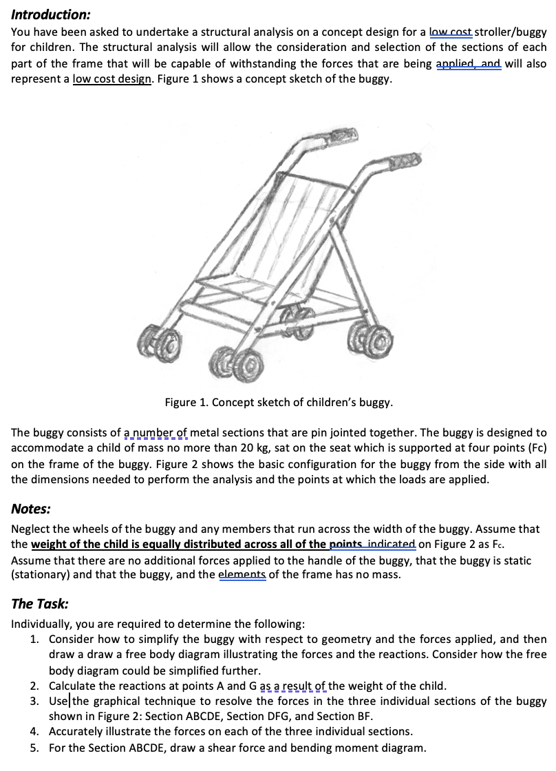
represent a low cost design. Figure shows a concept sketch of the buggy.
Figure Concept sketch of children's buggy.
The buggy consists of a number of metal sections that are pin jointed together. The buggy is designed to
accommodate a child of mass no more than sat on the seat which is supported at four points Fc
on the frame of the buggy. Figure shows the basic configuration for the buggy from the side with all
the dimensions needed to perform the analysis and the points at which the loads are applied.
Notes:
Neglect the wheels of the buggy and any members that run across the width of the buggy. Assume that
the weight of the child is equally distributed across all of the points indicated on Figure as F
Assume that there are no additional forces applied to the handle of the buggy, that the buggy is static
stationary and that the buggy, and the elements of the frame has no mass.
The Task:
Individually, you are required to determine the following:
Consider how to simplify the buggy with respect to geometry and the forces applied, and then
draw a draw a free body diagram illustrating the forces and the reactions. Consider how the free
body diagram could be simplified further.
Calculate the reactions at points A and as a result of the weight of the child.
Usethe graphical technique to resolve the forces in the three individual sections of the buggy
shown in Figure : Section ABCDE, Section DFG and Section BF
Accurately illustrate the forces on each of the three individual sections.
For the Section ABCDE, draw a shear force and bending moment diagram.
Step by Step Solution
There are 3 Steps involved in it
1 Expert Approved Answer
Step: 1 Unlock

Question Has Been Solved by an Expert!
Get step-by-step solutions from verified subject matter experts
Step: 2 Unlock
Step: 3 Unlock