

Question: IPv 6 addressing Addressing Table Step 1 : Determine the IP Addressing Scheme. Desian an IPv 4 addressina scheme and complete the Addressina Table based
IPv addressing
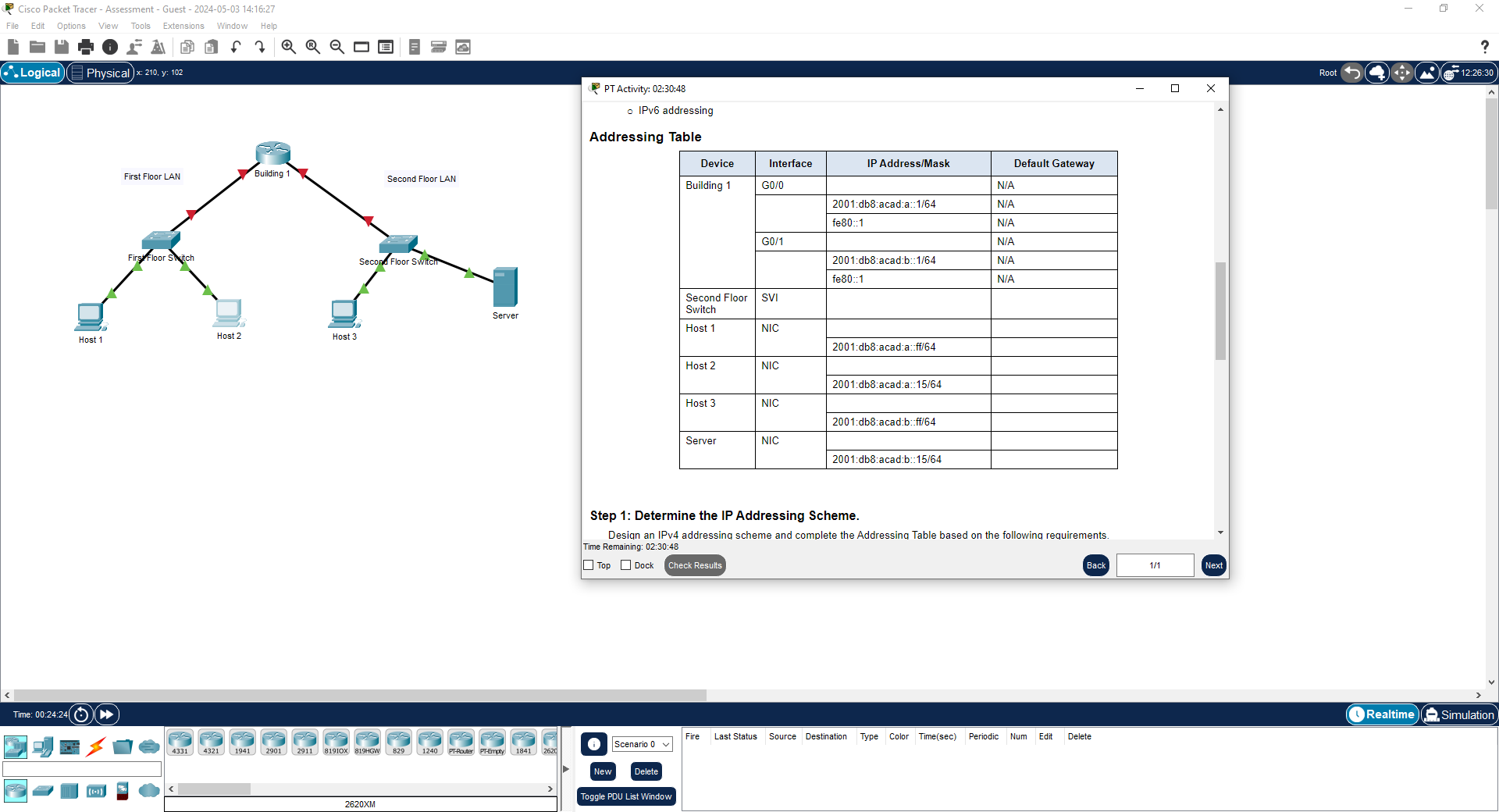
Addressing Table
Step : Determine the IP Addressing Scheme.
Desian an IPv addressina scheme and complete the Addressina Table based on the following requirements.
Time Remaining: ::
Top
DockYou will practice and be assessed on the following skills:
Configuration of initial IOS device settings
Design and calculation of IPv addressing
Configuration of IOS device interfaces including IPv and IPv addressing when appropriate
Addressing of network hosts with IPv and IPv addresses
Enhancing device security, including configuration of the secure transport protocol for remote device management
Configuration of a switch virtual management interface
Requirements by device:
Building router:
Configuration of initial router settings
Interface configuration and IPv and IPv addressing
Device security enhancement, or device hardening
Secure transport for remote configuration connections as covered in the labs and Packet Tracers in the course.
Second Floor Switch:
Enabling basic remote management by Telnet
PC and Server hosts:
o IPv full addressing
o IPv addressingStep : Determine the IP Addressing Scheme.
Design an IPv addressing scheme and complete the Addressing Table based on the following requirements.
a Subnet the network to provide host addresses per subnet while wasting the fewest addresses.
b Assign the fourth subnet to the First Floor LAN.
c Assign the last network host address the highest in this subnet to the G interface on Building
d Starting with the fifth subnet, subnet the network again so that the new subnets will provide host addresses per subnet while wasting the fewest addresses.
e Assign the second of these new host subnets to the Second Floor LAN.
f Assign the last network host address the highest in the Second Floor LAN subnet to the G interface of the Building router.
g Assign the second to the last address the second highest in this subnet to the VLAN interface of the Second Floor Switch.
h Configure addresses on the hosts using any of the remaining addresses in their respective subnets.
Step : Configure Host Addressing
a Use the IPv addressing from Step and the IPv addressing values provided in the Addressing Table to configure all host PCs with the correct addressing.
b Use the router interface linklocal address as the IPv default gateways on the hosts.
c Complete the configuration of the server using the IPv addressing values from Step and the values in the addressing table
Step : Configure the Building Router.
a Configure the Building router with all initial configurations that you have learned in the course so far:
o Configure the router hostname: Building
o Protect device configurations from unauthorized access with the encrypted privileged exec password.
o Secure all access lines into the router using methods covered in the course and labs.
o Require newlyentered passwords to have a minimum length of characters.
o Prevent all passwords from being viewed in clear text in device configuration files.
o Configure the router to only accept inband management connections over the protocol that is more secure than Telnet, as was done in the labs and PT activities. Use the value for encryption key strength.
o Configure local user authentication for inband management connections. Create a user with the name netadmin and a secret password of CiscoCCNA
b Configure the two Gigabit Ethernet interfaces using the IPv addressing values that you calculated and the IPv values provided in the addressing table.
o Reconfigure the link local addresses to the value shown in the table.
o Document the interfaces in the configuration file.
Step : Configure the Second Floor Switch.
Configure Second Floor Switch for remote management over Telnet.
a Configure VLAN as the SVI.
b Configure IPv addressing according to your work in Step
c Be sure that the switch is able to accept connections from hosts on other networks.
Step by Step Solution
There are 3 Steps involved in it
1 Expert Approved Answer
Step: 1 Unlock

Question Has Been Solved by an Expert!
Get step-by-step solutions from verified subject matter experts
Step: 2 Unlock
Step: 3 Unlock