

Question: ITNW-2421 Addressing Table: Device Interface IP Address Subnet Mask Default Gateway Switch Port VLAN Main VLAN 10 192.168.10.1 255.255.255.0 N/A N/A N/A VLAN 20 192.168.20.1
ITNW-2421
Addressing Table:
| Device | Interface | IP Address | Subnet Mask | Default Gateway | Switch Port | VLAN |
|
Main | VLAN 10 | 192.168.10.1 | 255.255.255.0 | N/A | N/A | N/A |
| VLAN 20 | 192.168.20.1 | 255.255.255.0 | N/A | N/A | N/A | |
| VLAN 88 | 192.168.88.1 | 255.255.255.0 | N/A | N/A | N/A | |
| West | VLAN 88 | 192.168.88.2 | 255.255.255.0 | 192.168.88.1 | N/A | N/A |
| South | VLAN 88 | 192.168.88.3 | 255.255.255.0 | 192.168.88.1 | N/A | N/A |
| Lab1 | NIC | 192.168.10.50 | 255.255.255.0 | 192.168.10.1 | West Fa0/1 | 10 |
| Lab2 | NIC | 192.168.10.51 | 255.255.255.0 | 192.168.10.1 | South Fa0/1 | 10 |
| Office1 | NIC | 192.168.20.50 | 255.255.255.0 | 192.168.20.1 | West Fa0/11 | 20 |
| Server | NIC | 192.168.20.5 | 255.255.255.0 | 192.168.20.1 | South Fa0/11 | 20 |
| Office2 | NIC | 192.168.20.51 | 255.255.255.0 | 192.168.20.1 | South Fa0/12 | 20 |
Scenario:
VLANs and EtherChannel need to be implemented in your network. Routing between the VLANs will be supported by the layer 3 switch Main. Once the EtherChannels are created, the root bridge for VLAN 10 will be changed to Main.
Instructions:
Configure IP addressing for all end devices and access layer switches (West and South) according to the Addressing Table above.
| VLAN ID | Name | Assigned Ports |
| 10 | Students | Fa0/1 - Fa0/10 |
| 20 | Staff | Fa0/11 - Fa0/20 |
| 88 | Management |
|
Configure VLANs:
- In all switches, create the VLANs according to the table above.
- In switches West and South, configure ports Fa0/1 - Fa0/20 as access ports and assign them to each VLAN according to the table above. (VLAN 88 has no ports assigned).
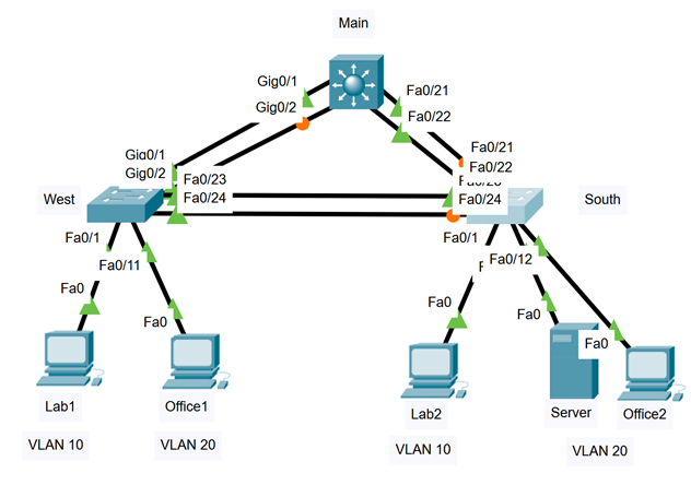
| Channel Group | Ports | Protocol |
| 1 | Main: G0/1, G0/2 West: G0/1, G0/2 | PAgP |
| 2 | Main: Fa0/21, Fa0/22 South: Fa0/21, Fa0/22 | LACP |
| 3 | West: Fa0/23, Fa0/24 South: Fa0/23, Fa0/24 | PAgP |
Configure EtherChannel:
- Create the port channels groups according to the table above.
- Configure each port channel interface as trunk.
- Assign Natvie VLAN 99 to each trunk
Note: on switch Main, you have to configure the trunk encapsulation before you can set the port channel interface as trunk. To configure the trunk encapsulation, type the command:
Main(config-if)#switchport trunk encapsulation dot1q
Configure Inter-VLAN Routing:
- Enable IPv4 routing
- Configure all SVI interfaces on Main
Configure the root bridge for VLAN 10:
- By default, West will be selected as the root bridge. To balance the load, configure Main to be the root bridge for VLAN 10. (Refer to PT 6.2.4)
When the network is fully configured, all devices should be able to ping each other.
Main Gig0/1 Gig0/2 Fa0/21 Fa0/22 Gia0/1 Gig012 Fa0/23 Fa0/21 Fa0/22 Funicu Fa0/24 West Fa0/24 South Fa0/1 Fa0/1 Fa0/11 Fao Fa0/12 Fao Fao Fao Fao Lab1 Office1 Lab2 Server Office2 VLAN 10 VLAN 20 VLAN 10 VLAN 20 Main Gig0/1 Gig0/2 Fa0/21 Fa0/22 Gia0/1 Gig012 Fa0/23 Fa0/21 Fa0/22 Funicu Fa0/24 West Fa0/24 South Fa0/1 Fa0/1 Fa0/11 Fao Fa0/12 Fao Fao Fao Fao Lab1 Office1 Lab2 Server Office2 VLAN 10 VLAN 20 VLAN 10 VLAN 20
Step by Step Solution
There are 3 Steps involved in it

Get step-by-step solutions from verified subject matter experts