

Question: Just answer problem 2.28 a I just attached the example for ref. Problem 2.28a Example 2.9 shows the calculated thickness at the bottom needed for
Just answer problem 2.28 a I just attached the example for ref.
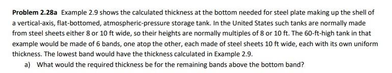
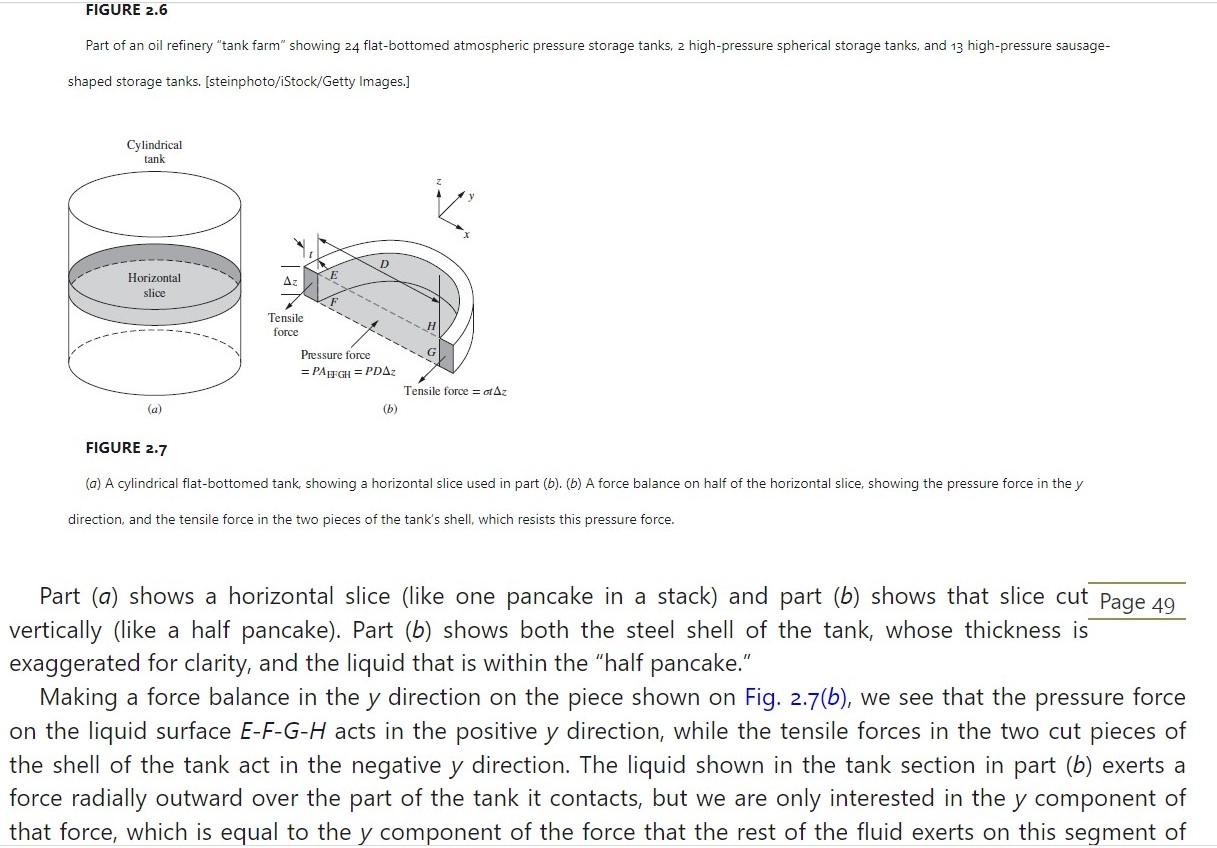
Problem 2.28a Example 2.9 shows the calculated thickness at the bottom needed for steel plate making up the shell of a vertical-axis, flat-bottomed, atmospheric-pressure storage tank. In the United States such tanks are normally made from steel sheets either 8 or 10ft wide, so their heights are normally multiples of 8 or 10ft. The 60 -ft-high tank in that example would be made of 6 bands, one atop the other, each made of steel sheets 10ft wide, each with its own uniform thickness. The lowest band would have the thickness calculated in Example 2.9. a) What would the required thickness be for the remaining bands above the bottom band? Part of an oil refinery "tank farm" showing 24 flat-bottomed atmospheric pressure storage tanks, 2 high-pressure spherical storage tanks, and 13 high-pressure sausage- shaped storage tanks. [steinphoto/iStock/Getty Images.] FIGURE 2.7 (a) A cylindrical flat-bottomed tank, showing a horizontal slice used in part (b). (b) A force balance on half of the horizontal slice, showing the pressure force in the y direction, and the tensile force in the two pieces of the tank's shell, which resists this pressure force. Part (a) shows a horizontal slice (like one pancake in a stack) and part (b) shows that slice cut Page 49 vertically (like a half pancake). Part (b) shows both the steel shell of the tank, whose thickness is exaggerated for clarity, and the liquid that is within the "half pancake." Making a force balance in the y direction on the piece shown on Fig. 2.7(b), we see that the pressure force on the liquid surface EFGH acts in the positive y direction, while the tensile forces in the two cut pieces of the shell of the tank act in the negative y direction. The liquid shown in the tank section in part (b) exerts a force radially outward over the part of the tank it contacts, but we are only interested in the y component of that force, which is equal to the y component of the force that the rest of the fluid exerts on this segment of that force, which is equal to the y component of the force that the rest of the fluid exerts on this segment of fluid. We do not bother with forces in the x or z directions, because they do not concern us here. If the tank is not in the act of rupturing, then the sum of the forces in the y direction (or any other) must be zero, so we may write PDz=2ensilezt where ensile is the tensile stress in the shell, P is the gauge pressure, also assumed to be uniform, and t is the thickness of the metal shell. Now we make the thin-walled assumption that ensile is uniform over the wall thickness (see below). Solving for the required thickness of the shell, we find t=2tensilePD[cylindrical,thin-walledassumption] The tensile stress in Eq. 2.25 is resisted by the external metal hoops in barrels and in wooden water tanks; it is normally called the hoop stress. Example 2.9. If the design tensile stress (normally 1/4 of the stress at rupture) of the tank wall is 20 ooo psia, how thick must the shell of the tank in Example 2.3 be at the bottom of the tank? The diameter of the tank is 120ft. Substituting directly into Eq. 2.25, we write t=220000lbf/in2(22.9lbf/in2)120ft=0.0688ft=0.825in=2.10cm
Step by Step Solution
There are 3 Steps involved in it

Get step-by-step solutions from verified subject matter experts