

Question: Just Solved only in (Verilog code module ). Both shift and rotate could be performed on stages by positions power of 2 (1,2,4) **notes:he
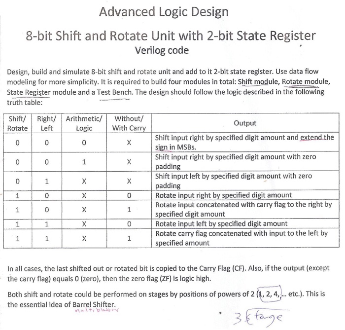
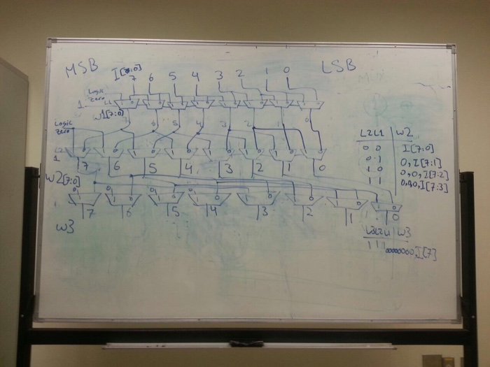
Advanced Logic Design 8-bit Shift and Rotate Unit with 2-bit State Register Verilog code Design, build and simulate 8-bit shift and rotate unit and add to it 2-bit state register. Use data flow modeling for more simplicity. It is required to build four modules in total: Shift module, Rotate module, State Register module and a Test Bench. The design should follow the logic described in the following truth table Shift/ Right/ Arithmetic/Without,/ Rotate Left Output Logic With Car Shift input right by specified digit amount and extend the sign in MSBs. Shift input right by specified digit amount with zero addin Shift input left by specified digit amount with zero adding Rotate input right by specified digit amount Rotate input concatenated with carry flag to the right by specified digit amount Rotate input left by specified digit amount Rotate carry flag concatenated with input to the left by specified amount 0 In all cases, the last shifted out or rotated bit is copied to the Carry Flag (CF). Also, if the output (except the carry flag) equals 0 (zero), then the zero flag (ZF) is logic high. Both shift and rotate could be performed on stages by positions of powers of 2 (1, 2, 4, etc.). This is the essential idea of Barrel Shifter
Step by Step Solution
There are 3 Steps involved in it

Get step-by-step solutions from verified subject matter experts