

Question: K Clock pulse Figure 24 Note: If you do not have enough spare gates to complete this diagram, remember that other gates can be transformed
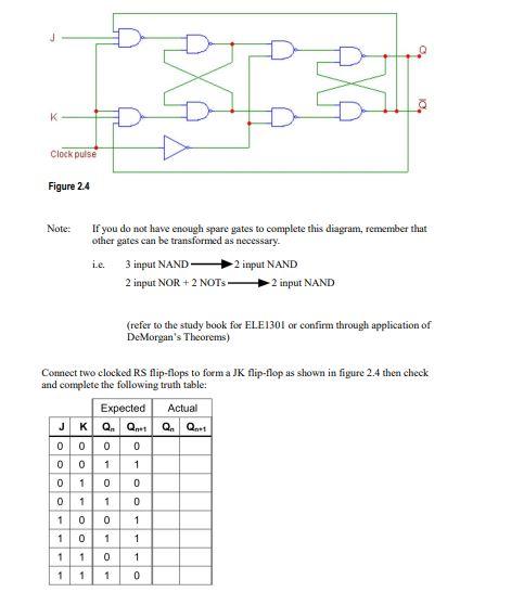
K Clock pulse Figure 24 Note: If you do not have enough spare gates to complete this diagram, remember that other gates can be transformed as necessary. i.e. 3 input NAND input NAND 2 input NOR + 2 NOTS- 2 input NAND (refer to the study book for ELE1301 or confirm through application of De Morgan's Theorems) Connect two clocked RS flip-flops to form a JK flip-flop as shown in figure 2.4 then check and complete the following truth table: Expected Actual JKQ. Q. Q. Q.t 0 0 0 0 0 0 1 1 0 1 0 0 1 1 1 0 0 1 1 0 1 oo- 0 1 1 0 1 1 1 1 0
Step by Step Solution
There are 3 Steps involved in it
1 Expert Approved Answer
Step: 1 Unlock

Question Has Been Solved by an Expert!
Get step-by-step solutions from verified subject matter experts
Step: 2 Unlock
Step: 3 Unlock