

Question: k maps implementation for a Q1: There are three switches in a room labeled S1, S2 and S3 which connect to one Light. All the
k maps implementation for a
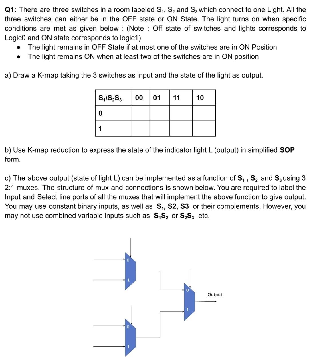
Q1: There are three switches in a room labeled S1, S2 and S3 which connect to one Light. All the three switches can either be in the OFF state or ON State. The light turns on when specific conditions are met as given below : (Note : Off state of switches and lights corresponds to Logico and ON state corresponds to logic1) The light remains in OFF State if at most one of the switches are in ON Position The light remains ON when at least two of the switches are in ON position . a) Draw a K-map taking the 3 switches as input and the state of the light as output. SISS 00 01 11 10 0 1 b) Use K-map reduction to express the state of the indicator light L (output) in simplified SOP form. c) The above output (state of light L) can be implemented as a function of S, , Sand S; using 3 2:1 muxes. The structure of mux and connections is shown below. You are required to label the Input and Select line ports of all the muxes that will implement the above function to give output. You may use constant binary inputs, as well as S1, S2, S3 or their complements. However, you may not use combined variable inputs such as S,S, or SS3 etc. Output
Step by Step Solution
There are 3 Steps involved in it

Get step-by-step solutions from verified subject matter experts