

Question: Lab 5: Full adder and Binary adder design 1. Design a full adder. Be sure to use an optimized design. 2. Use the optimized
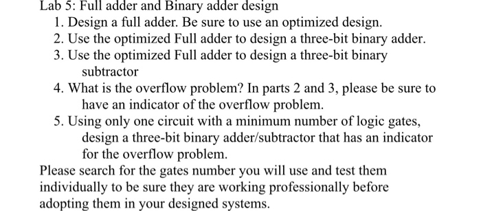
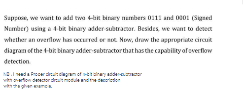
Lab 5: Full adder and Binary adder design 1. Design a full adder. Be sure to use an optimized design. 2. Use the optimized Full adder to design a three-bit binary adder. 3. Use the optimized Full adder to design a three-bit binary subtractor 4. What is the overflow problem? In parts 2 and 3, please be sure to have an indicator of the overflow problem. 5. Using only one circuit with a minimum number of logic gates, design a three-bit binary adder/subtractor that has an indicator for the overflow problem. Please search for the gates number you will use and test them individually to be sure they are working professionally before adopting them in your designed systems. Suppose, we want to add two 4-bit binary numbers 0111 and 0001 (Signed Number) using a 4-bit binary adder-subtractor. Besides, we want to detect whether an overflow has occurred or not. Now, draw the appropriate circuit diagram of the 4-bit binary adder-subtractor that has the capability of overflow detection. NB: I need a Proper circuit diagram of 4-bit binary adder-subtractor with overflow detector circuit module and the description with the given example.
Step by Step Solution
There are 3 Steps involved in it

Get step-by-step solutions from verified subject matter experts