

Question: Lab Experiment 6: Implementing a proportional Control system using MATLAB and Arduino Nano. Objectives: Students will be able to Regulate a system using a proportional
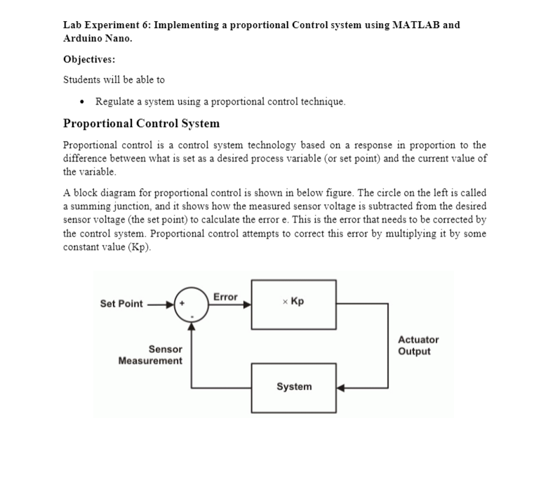
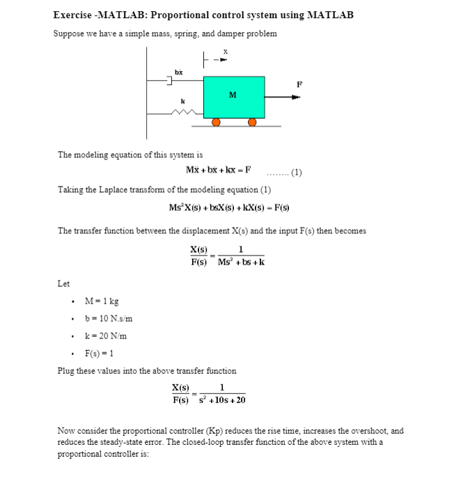
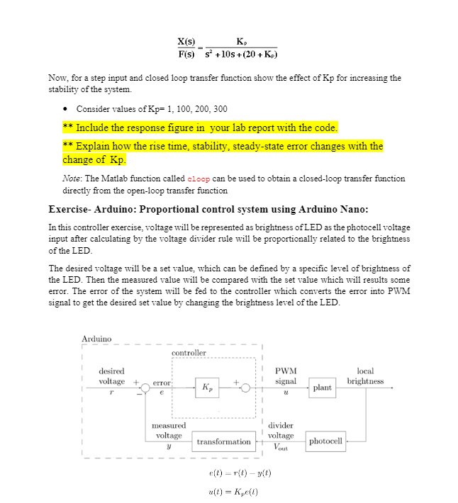
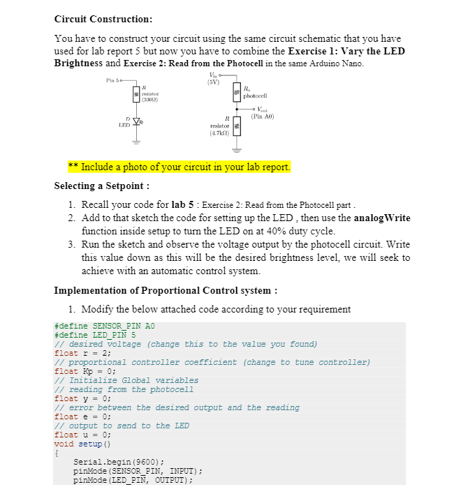
Lab Experiment 6: Implementing a proportional Control system using MATLAB and Arduino Nano. Objectives: Students will be able to Regulate a system using a proportional control technique. Proportional Control System Proportional control is a control system technology based on a response in proportion to the difference between what is set as a desired process variable (or set point) and the current value of the variable A block diagram for proportional control is shown in below figure. The circle on the left is called a summing junction, and it shows how the measured sensor voltage is subtracted from the desired sensor voltage (the set point) to calculate the error e. This is the error that needs to be corrected by the control system. Proportional control attempts to correct this error by multiplying it by some constant value (KP). Error Set Point x Sensor Measurement Actuator Output System Exercise - MATLAB: Proportional control system using MATLAB Suppose we have a simple mass, spring, and damper problem X bx 1 M The modeling equation of this system is Mx + bx + kx - F (1) Taking the Laplace transform of the modeling equation (1) MsX(s) + bsX(s) +kX(s) - F(s) The transfer function between the displacement X(s) and the input F() then becomes X(s) 1 F(s) Ms+bs+k Let M = 1 kg b = 10 N.s/m k = 20 N/m F(s) = 1 Plug these values into the above transfer function X(s) 1 F(s) +10s +20 Now consider the proportional controller (Kp) reduces the rise time, increases the overshoot, and reduces the steady-state error. The closed-loop transfer function of the above system with a proportional controller is: X(s) K F(s) s +10s +(20+Kp) Now, for a step input and closed loop transfer function show the effect of Kp for increasing the stability of the system Consider values of Kp= 1, 100, 200, 300 ** Include the response figure in your lab report with the code. * Explain how the rise time, stability, steady-state error changes with the change of Kp. Note: The Matlab function called cloop can be used to obtain a closed-loop transfer function directly from the open-loop transfer function Exercise-Arduino: Proportional control system using Arduino Nano: In this controller exercise, voltage will be represented as brightness of LED as the photocell voltage input after calculating by the voltage divider rule will be proportionally related to the brightness of the LED The desired voltage will be a set value, which can be defined by a specific level of brightness of the LED. Then the measured value will be compared with the set value which will results some error. The error of the system will be fed to the controller which converts the error into PWM signal to get the desired set value by changing the brightness level of the LED. Arduino controller desired voltage + PWM signal local brightness error K, plant measured voltage y divider voltage Vout transformation photocell e(t) = r(t) - (0) u(I) = K (1) Circuit Construction: You have to construct your circuit using the same circuit schematic that you have used for lab report 5 but now you have to combine the Exercise 1: Vary the LED Brightness and Exercise 2: Read from the Photocell in the same Arduino Nano. Pins (SV) sistor (300) photocell (Pin A0) LED R Tesistor (4.7) Include a photo of your circuit in your lab report. Selecting a Setpoint : 1. Recall your code for lab 5 : Exercise 2: Read from the Photocell part. 2. Add to that sketch the code for setting up the LED, then use the analogWrite function inside setup to turn the LED on at 40% duty cycle. 3. Run the sketch and observe the voltage output by the photocell circuit. Write this value down as this will be the desired brightness level, we will seek to achieve with an automatic control system. Implementation of Proportional Control system : 1. Modify the below attached code according to your requirement #define SENSOR_PIN AO #define LED_PIN 5 // desired voltage (change this to the value you found) float r = 2; // proportional controller coefficient (change to tune controller) float Kp = 0; // Initialize Global variables // reading from the photocell float y = 0; // error between the desired output and the reading float e = 0; // output to send to the LED float u = 0; void setup { Serial.begin(9600); pinMode (SENSOR_PIN, INPUT); pinMode(LED_PIN, OUTPUT); } void loop() { u = // store your measured voltage in this variable y = 1/ compute the error between the measurement and the desired value // compute the control effort by multiplying the error by Kp // make sure the output value is bounded to 0 to 255 using the bound function defined below u = bound(u, 0, 255); analogWrite(LED_PIN, u); // then write it to the LED pin to change control voltage to LED // plot the measurement using serial print // plot the desired output using serial print // plot the error using serial print 1/ Bound the input value between x_min and x_max. float bound (float x, float x_min, float x_max) { if (x x_max) { x = x_max; } return x; 2. Once the code is uploaded and running, open up the serial plotter. The series of Serial.print statements in the code plots the all the recorded 3 signals (Measured, referenced and error). The reference signal should be a constant. * Include a photo of your serial plotter output in report. 3. Let the signals become steady, then use the error measurement to make an estimate of what Kp should be to drive the error to zero. Now, recall the reference PWM signal to achieve 40% duty cycle (previous exercise). 4. Now try casting shadows over the circuit. Looking at the LED itself, does it seem to compensate when less light from the ambient environment hits the photocell? What do you observe when looking at the error signal in the serial plotter? * Include a photo of your serial plotter error output in report. Lab Experiment 6: Implementing a proportional Control system using MATLAB and Arduino Nano. Objectives: Students will be able to Regulate a system using a proportional control technique. Proportional Control System Proportional control is a control system technology based on a response in proportion to the difference between what is set as a desired process variable (or set point) and the current value of the variable A block diagram for proportional control is shown in below figure. The circle on the left is called a summing junction, and it shows how the measured sensor voltage is subtracted from the desired sensor voltage (the set point) to calculate the error e. This is the error that needs to be corrected by the control system. Proportional control attempts to correct this error by multiplying it by some constant value (KP). Error Set Point x Sensor Measurement Actuator Output System Exercise - MATLAB: Proportional control system using MATLAB Suppose we have a simple mass, spring, and damper problem X bx 1 M The modeling equation of this system is Mx + bx + kx - F (1) Taking the Laplace transform of the modeling equation (1) MsX(s) + bsX(s) +kX(s) - F(s) The transfer function between the displacement X(s) and the input F() then becomes X(s) 1 F(s) Ms+bs+k Let M = 1 kg b = 10 N.s/m k = 20 N/m F(s) = 1 Plug these values into the above transfer function X(s) 1 F(s) +10s +20 Now consider the proportional controller (Kp) reduces the rise time, increases the overshoot, and reduces the steady-state error. The closed-loop transfer function of the above system with a proportional controller is: X(s) K F(s) s +10s +(20+Kp) Now, for a step input and closed loop transfer function show the effect of Kp for increasing the stability of the system Consider values of Kp= 1, 100, 200, 300 ** Include the response figure in your lab report with the code. * Explain how the rise time, stability, steady-state error changes with the change of Kp. Note: The Matlab function called cloop can be used to obtain a closed-loop transfer function directly from the open-loop transfer function Exercise-Arduino: Proportional control system using Arduino Nano: In this controller exercise, voltage will be represented as brightness of LED as the photocell voltage input after calculating by the voltage divider rule will be proportionally related to the brightness of the LED The desired voltage will be a set value, which can be defined by a specific level of brightness of the LED. Then the measured value will be compared with the set value which will results some error. The error of the system will be fed to the controller which converts the error into PWM signal to get the desired set value by changing the brightness level of the LED. Arduino controller desired voltage + PWM signal local brightness error K, plant measured voltage y divider voltage Vout transformation photocell e(t) = r(t) - (0) u(I) = K (1) Circuit Construction: You have to construct your circuit using the same circuit schematic that you have used for lab report 5 but now you have to combine the Exercise 1: Vary the LED Brightness and Exercise 2: Read from the Photocell in the same Arduino Nano. Pins (SV) sistor (300) photocell (Pin A0) LED R Tesistor (4.7) Include a photo of your circuit in your lab report. Selecting a Setpoint : 1. Recall your code for lab 5 : Exercise 2: Read from the Photocell part. 2. Add to that sketch the code for setting up the LED, then use the analogWrite function inside setup to turn the LED on at 40% duty cycle. 3. Run the sketch and observe the voltage output by the photocell circuit. Write this value down as this will be the desired brightness level, we will seek to achieve with an automatic control system. Implementation of Proportional Control system : 1. Modify the below attached code according to your requirement #define SENSOR_PIN AO #define LED_PIN 5 // desired voltage (change this to the value you found) float r = 2; // proportional controller coefficient (change to tune controller) float Kp = 0; // Initialize Global variables // reading from the photocell float y = 0; // error between the desired output and the reading float e = 0; // output to send to the LED float u = 0; void setup { Serial.begin(9600); pinMode (SENSOR_PIN, INPUT); pinMode(LED_PIN, OUTPUT); } void loop() { u = // store your measured voltage in this variable y = 1/ compute the error between the measurement and the desired value // compute the control effort by multiplying the error by Kp // make sure the output value is bounded to 0 to 255 using the bound function defined below u = bound(u, 0, 255); analogWrite(LED_PIN, u); // then write it to the LED pin to change control voltage to LED // plot the measurement using serial print // plot the desired output using serial print // plot the error using serial print 1/ Bound the input value between x_min and x_max. float bound (float x, float x_min, float x_max) { if (x x_max) { x = x_max; } return x; 2. Once the code is uploaded and running, open up the serial plotter. The series of Serial.print statements in the code plots the all the recorded 3 signals (Measured, referenced and error). The reference signal should be a constant. * Include a photo of your serial plotter output in report. 3. Let the signals become steady, then use the error measurement to make an estimate of what Kp should be to drive the error to zero. Now, recall the reference PWM signal to achieve 40% duty cycle (previous exercise). 4. Now try casting shadows over the circuit. Looking at the LED itself, does it seem to compensate when less light from the ambient environment hits the photocell? What do you observe when looking at the error signal in the serial plotter? * Include a photo of your serial plotter error output in report
Step by Step Solution
There are 3 Steps involved in it

Get step-by-step solutions from verified subject matter experts