

Question: LAB: VLAN CONFIGURATION table [ [ Addressing Table ] , [ table [ [ Device ] , [ ( Hestname ) ] ]
LAB: VLAN CONFIGURATION
tableAddressing TabletableDeviceHestnameInterface,IP Addras:,Subnet Mask,Deftault Gateway$VAN NVA$VAN NAVAN NAPCNIC,PCNIC,PcMiC,PCNiC,PCNiC,PCNIC,
Task : Prepare the Network
Create a network same as the one in the topology diagram above in Cisco Packet Tracer. You can use any switch if it has the required interfaces shown in the topology.
For each switch set the hostname in config tab and then use the following commands. For example, for $ :
int vlan
ip address
Task :
Step : Disable unused ports on the switches
It is a good practice to disable any unused ports on the switches by putting them in shutdown. Disable all ports on the switches:
First enable the switch by using command enable.
Switch#config term
Switchconfig #interface range fa
Switch configifrange #shutdown
Switch configifrange #interface range gi
Switch configifrange #shutdown
Take a screenshot of you commands and put it in the word document.
Step : Reenable the user ports on switch:
config# interface range fa fa
Sconfigifrange# switchport mode access
Sconfigifrange# no shutdown
Take a screenshot of you commands and put it in the word document.
Task : Configure VLANs on the Switch
Step : Create VLANs on switch S
There are four VLANS configured for this lab: VLAN facultystaff; VLAN students; VLAN guest; and VLAN management After you create the VLAN, you will be in vlan configuration mode, where you can assign a name to the VLAN with the name vlan name command.
Sconfig #van
Sconfigvlan Hname facultystaff
Sconfigvlan #van
Sconfigvlan #name students
Sconfigvlan #van
Sconfigvlan #name guest
Sconfigvlan #van
Sconfigvlan finame management
Sconfigvlan #end
S#
Step : Verify that the VLANs have been created on S
Use the show vlan command. Take a screenshot and put it in your word document.
show vlan VLAN Name
tableVLANNane,Status,Portsdefault,active,facultystaffactive,tablestudentsactive,guest,active,management,active,
Step : Configure and name VLANs on switches S and S
Create and name VLANs and on S and S using the commands from Step
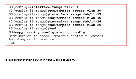
Step : Assign switch ports to VLANs on S
You can assign each port individually or you can use the interface range command to simplify this task, as shown here. First use the command config term. Then type the commands below:
Take a screenshot and put it in your word document.
Step by Step Solution
There are 3 Steps involved in it
1 Expert Approved Answer
Step: 1 Unlock

Question Has Been Solved by an Expert!
Get step-by-step solutions from verified subject matter experts
Step: 2 Unlock
Step: 3 Unlock