

Question: laboratory physics an caprunebut actup with a capacitive sensor, C... 10 pf, is connected to a volumeter by a pair of copper cables. The voltmeter
laboratory physics
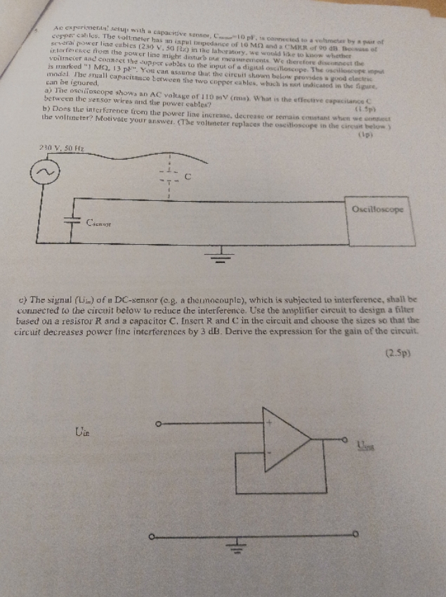
an caprunebut actup with a capacitive sensor, C... 10 pf, is connected to a volumeter by a pair of copper cables. The voltmeter has an inpul impedance of 10 M and a CMIR of 90 di Bycause of several power line cubles (230 v. 50 fix) in the laboratory. we would like to know whether interference nom the power line might disturb our measurements. We there fore disconnect the voilmeter and connect the supper cables to the input of a digital oscilloscope, The oscilloscope input is marked "] MO. 13 pl". You can assume that the circuit shown below provides a good electric nidal. The small capacitance between the two copper cables, which is not indicated in the figure. can be ignored, aj The oscuffoscope shows an AC voltage of 1 10 my (rens; What is the effective capacitance C between the sensor wires and the power cable? by Does the interference from the power line increase, decrease or remain constant when we ennugget the voltmeter? Motivate your answer. (The volumeter replaces the oscilloscope in the circuit below (Ip) 230 V. 50 Hz Oscilloscope c) The signal (Uin) of a DC-sensor (c.g, a thermocouple), which is subjected to interference, shall be connected to the circuit below to reduce the interference. Use the amplifier circuit to design a filter based on a resistor R and a capacitor C. Insert R. and C in the circuit and choose the sizes so that the circuit decreases power line interferences by 3 dB. Derive the expression for the gain of the circuit. (2.5p) Uin
Step by Step Solution
There are 3 Steps involved in it

Get step-by-step solutions from verified subject matter experts