

Question: LOGISIM PROBLEM--- **NEED ATLEAST THE TABLE FILLED OUT*** Replace the bus controls contents with a ROM, but leave the multiplexer alone, as show below: The
LOGISIM PROBLEM---
**NEED ATLEAST THE TABLE FILLED OUT***
Replace the bus controls contents with a ROM, but leave the multiplexer alone, as show below:
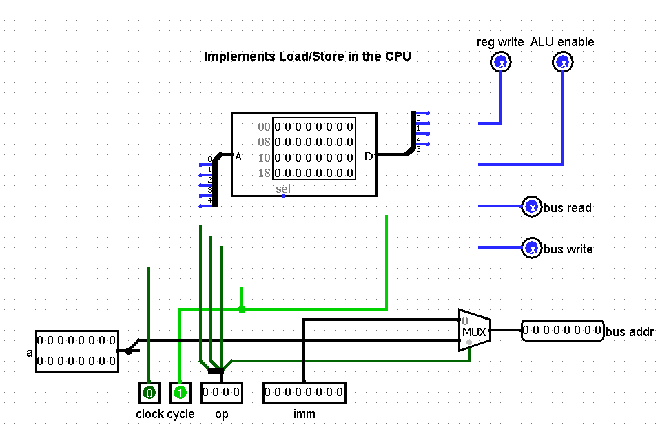
The ROM should have 5 input (address) bits (corresponding to clock, cycle and ops 3 MSBs), and 4 output (data) bits (corresponding to reg write, ALU enable, bus read, bus write). We dont need the least significant bit of the opcode, because it does not influence the output in any way.
Hint: poke on inputs to see what the corresponding output is, and note that in the table below. Then, take that table, and program (and connect) the ROM accordingly.
| Note | Theres no state involved, its purely combinational. |
| Important | Test your CPU to ensure that your code from the prior lab is still functional. If not, you goofed up. |
| ROM address | Op3 | Op2 | Op1 | Cycle | Clock | Reg write | ALU enable | Bus read | Bus write | |
|---|---|---|---|---|---|---|---|---|---|---|
| 0 | 0 | 0 | 0 | 0 | 0 | |||||
| 1 | 0 | 0 | 0 | 0 | 1 | |||||
| 2 | 0 | 0 | 0 | 1 | 0 | |||||
| 3 | 0 | 0 | 0 | 1 | 1 | |||||
| 4 | 0 | 0 | 1 | 0 | 0 | |||||
| 5 | 0 | 0 | 1 | 0 | 1 | |||||
| 6 | 0 | 0 | 1 | 1 | 0 | |||||
| 7 | 0 | 0 | 1 | 1 | 1 | |||||
| 8 | 0 | 1 | 0 | 0 | 0 | |||||
| 9 | 0 | 1 | 0 | 0 | 1 | |||||
| 10 | 0 | 1 | 0 | 1 | 0 | |||||
| 11 | 0 | 1 | 0 | 1 | 1 | |||||
| 12 | 0 | 1 | 1 | 0 | 0 | |||||
| 13 | 0 | 1 | 1 | 0 | 1 | |||||
| 14 | 0 | 1 | 1 | 1 | 0 | |||||
| 15 | 0 | 1 | 1 | 1 | 1 | |||||
| 16 | 1 | 0 | 0 | 0 | 0 | |||||
| 17 | 1 | 0 | 0 | 0 | 1 | |||||
| 18 | 1 | 0 | 0 | 1 | 0 | |||||
| 19 | 1 | 0 | 0 | 1 | 1 | |||||
| 20 | 1 | 0 | 1 | 0 | 0 | |||||
| 21 | 1 | 0 | 1 | 0 | 1 | |||||
| 22 | 1 | 0 | 1 | 1 | 0 | |||||
| 23 | 1 | 0 | 1 | 1 | 1 | |||||
| 24 | 1 | 1 | 0 | 0 | 0 | |||||
| 25 | 1 | 1 | 0 | 0 | 1 | |||||
| 26 | 1 | 1 | 0 | 1 | 0 | |||||
| 27 | 1 | 1 | 0 | 1 | 1 | |||||
| 28 | 1 | 1 | 1 | 0 | 0 | |||||
| 29 | 1 | 1 | 1 | 0 | 1 | |||||
| 30 | 1 | 1 | 1 | 1 | 0 | |||||
| 31 | 1 | 1 | 1 | 1 | 1 |
Step by Step Solution
There are 3 Steps involved in it

Get step-by-step solutions from verified subject matter experts