

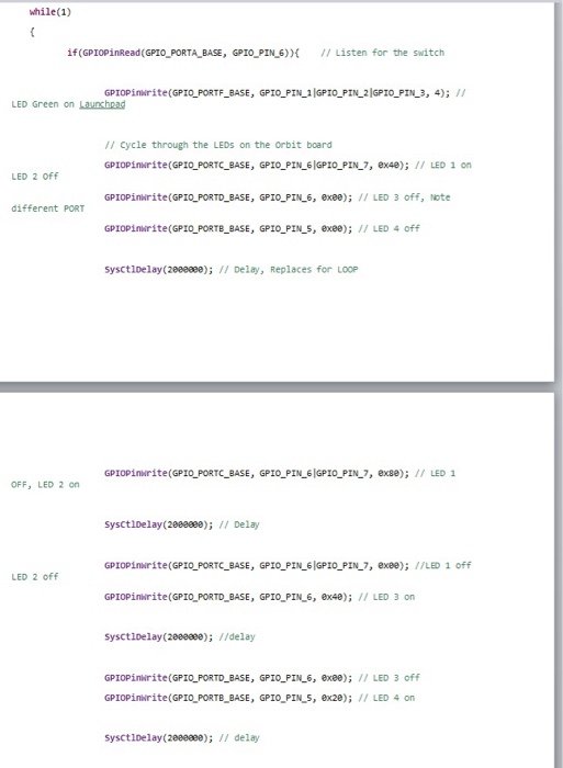
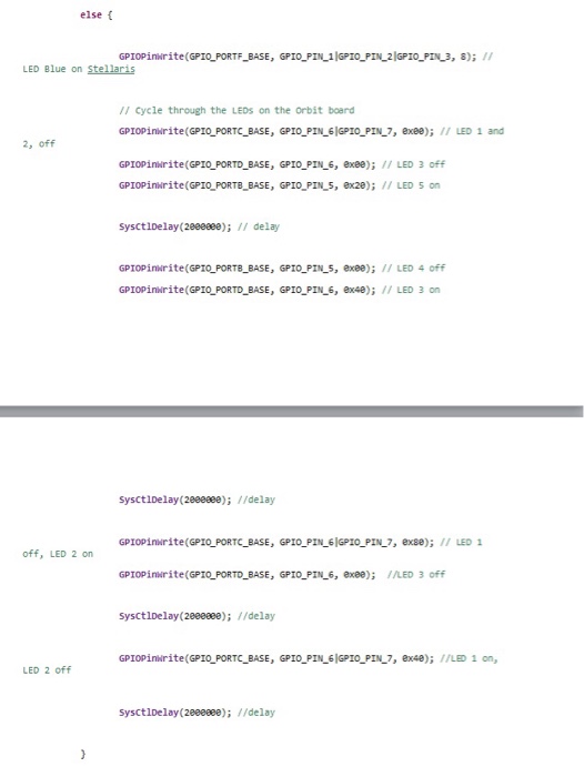
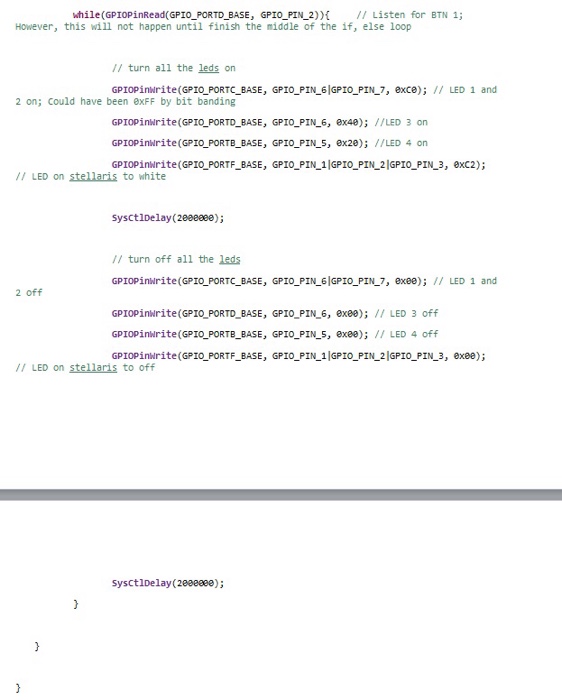
Question: Make a flow chart for the following source code: (Please be detailed in thorough in chart, read code carfully) void main(void) // setting the internal
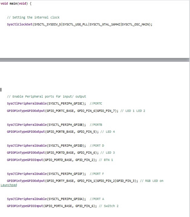
void main(void) // setting the internal clock SysctlclockSet (SYSCTL_SYSDIV_5|SYSCTL_USE PLLISYSCTL XTAL _16MHZISYSCTL OSC MAIN); // Enable Peripheral ports for input/ output sysctiperipheralEnable(SYSCTL PERIPH_GPIOC) /PORTC GPIOPinTypeGPIOOutput (GPIO_PORTC BASE, GPIO_PIN_61GPIO_PIN 7); // LED 1 LED 2 SysctiperipheralEnable(SYSCTL PERIPH_GPIOB) I/PORTB GPIOPinTypeGPIoOutput (GPIO_PORTB BASE, GPIO PIN 5); // LED 4 SysctiperipheralEnable(SYSCTL PERIPH_GPID) //PORT D GPIOPInTypeGPIooutput (GPIO_PORTD_BASE, GPIO PIN 6)/ LED 3 GPIOPinTypeGPIOImput (GPIO_PORTD BASE, GPTO_PIN 2); BTN 1 sysctiperipheralEnable(SYSCTL PERIPH_GPIOF) 1/PORT GPIOPInTypeGPIOOutput (GPIO_PORTF_BASE, GPIO_PIN 1|GPIO_PIN 2|GPIO_PIN 3); / RGB LED on sysctiperipheralEnable (SYSCTL PERIPH_GPIOA); //PORT A GPIOPinTypeGPIOImput (GPTO_PORTA BASE, GPTO_PIN 6); Switch 2
Step by Step Solution
There are 3 Steps involved in it

Get step-by-step solutions from verified subject matter experts