

Question: mation out. - You are tasked to create a traffic controller Mealy state machines. There will be THREE SEPARATE machines, and their descriptions will be
mation out.
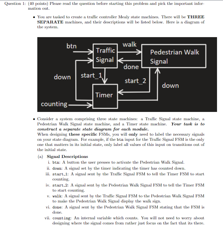
You are tasked to create a traffic controller Mealy state machines. There will be THREE SEPARATE machines, and their descriptions will be listed below. Here is a diagram of the system.
Consider a system comprising three state machines: a Traffic Signal state machine, a Pedestrian Walk Signal state machine, and a Timer state machine. Your task is to construct a separate state diagram for each module.
When designing these specific FSMs you will only need to label the necessary signals on your state diagram. For example, if the btn input for the Traffic Signal FSM is the only one that matters in its initial state, only label all values of this input on transitions out of the initial state.
a Signal Descriptions
i btn: A button the user presses to activate the Pedestrian Walk Signal.
ii down: A signal set by the timer indicating the timer has counted down.
iii. start: A signal sent by the Traffic Signal FSM to tell the Timer FSM to start counting.
iv start: A signal sent by the Pedestrian Walk Signal FSM to tell the Timer FSM to start counting.
v walk: A signal sent by the Traffic Signal FSM to the Pedestrian Walk Signal FSM to make the Pedestrian Walk Signal display the walk sign.
vi done: A signal sent by the Pedestrian Walk Signal FSM stating that the FSM is done.
vii. counting: An internal variable which counts. You will not need to worry about designing where the signal comes from rather just focus on the fact that its there.
b Traffic Signal FSM:
This state machine should only need THREE states. Assume the light is initially
GREEN. When the btn is pressed ie HIGH then the light should turn YELLOW,
and at the same time, start should transition to HIGH. When the down signal is
set to HIGH by the Timer FSM then the light should go RED. When the done signal
is set to HIGH by the Pedestrian Walk Signal, then the light should turn GREEN,
and walk should be LOW. Otherwise, walk should be HIGH, and the light should stay
RED.
c Pedestrian Walk Signal FSM:
This state machine should only need THREE states. Assume the Signal initially
displays a STOP symbol. If this module sees that walk is set to HIGH, then the
Pedestrian Walk Signal should display a walking symbol ie a person and should
set start to HIGH. Once the Pedestrian Walk Signal sees down transitions to HIGH,
then the Pedestrian Walk Signal should start counting down and set the start to
HIGH ; otherwise, the sign should keep showing a person. Once down has been set to
HIGH again, the Pedestrian Walk Signal should display a STOP symbol and set done
to HIGH.
d Timer FSM:
This state machine should only need TWO states. Assume the timer starts off waiting
for either start or start to go HIGH, set by the Traffic Signal or Pedestrian
Walk Signal. Once either start or start goes HIGH, then the timer should
count, and once the internal signal counting returns to LOW, the timer returns to its
idlewaiting state waiting for either start or start to go HIGH again. However,
before returning to its idlewaiting state, down should be HIGH. Otherwise, the timer
should keep counting if counting is not done ie HIGH
Can you draw them out on paper and make it as detailand clear as possible on each state?
Step by Step Solution
There are 3 Steps involved in it
1 Expert Approved Answer
Step: 1 Unlock

Question Has Been Solved by an Expert!
Get step-by-step solutions from verified subject matter experts
Step: 2 Unlock
Step: 3 Unlock