

Question: Matlab code of the question using the function I already wrote 1.5 points) Use your Sigma-Delta modulator to process a direct current (DC) signal. (0.5
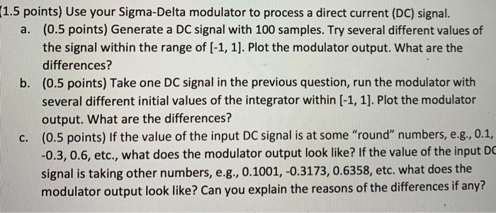
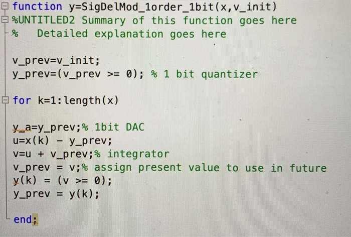
1.5 points) Use your Sigma-Delta modulator to process a direct current (DC) signal. (0.5 points) Generate a DC signal with 100 samples. Try several different values of the signal within the range of [-1, 1]. Plot the modulator output. What are the differences? (0.5 points) Take one DC signal in the previous question, run the modulator with several different initial values of the integrator within [-1, 1]. Plot the modulator output. What are the differences? (0.5 points) If the value of the input DC signal is at some "round" numbers, eg, 0.1, -0.3, 0.6, etc., what does the modulator output look like? If the value of the input DO signal is taking other numbers, e.g, 0.1001, -0.3173, 0.6358, etc. what does the modulator output look like? Can you explain the reasons of the differences if any? a. b. c. function y-SigDe lMod_1order_1bit(x,v_init) UNTITLED2 Summary of this function goes here 9% Detailed explanation goes here v_prev-v init; y-prev= (v-prev 0); % 1 bit quantizer >= E for k-1: length(x) y_asy-prev ; % 1bit DAC u x(k) -yprev; v=u + v-prev ; % integrator v-prev v;% assign present y(k) = (v >= 0); y-prev = y(k); value to use in future end
Step by Step Solution
There are 3 Steps involved in it

Get step-by-step solutions from verified subject matter experts