

Question: MCH 3 0 0 8 PROJECT 1 . 1 Question 1 : In the following figure the force F ( t ) is applied to
MCH PROJECT
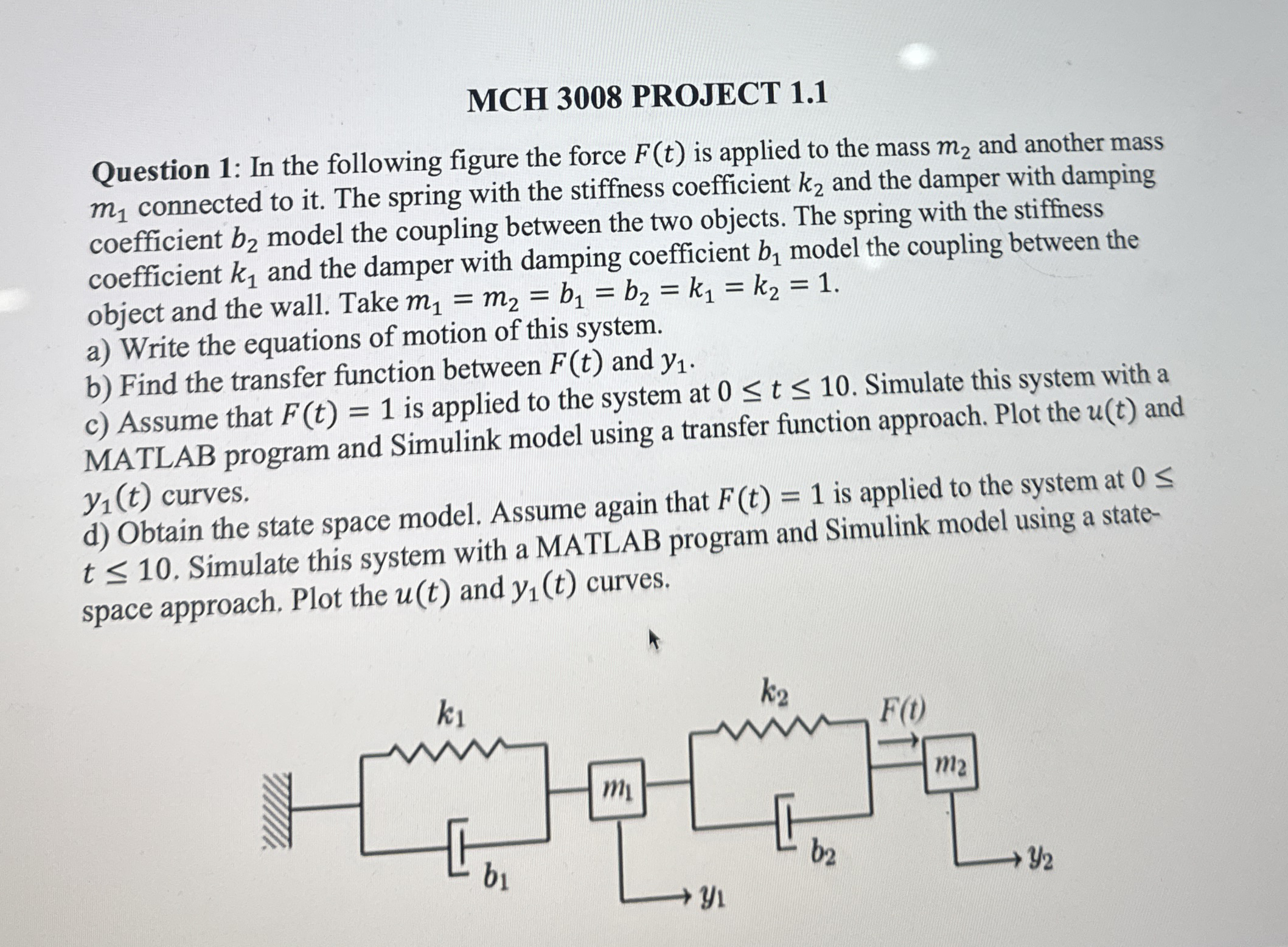
Question : In the following figure the force is applied to the mass and another mass connected to it The spring with the stiffness coefficient and the damper with damping coefficient model the coupling between the two objects. The spring with the stiffness coefficient and the damper with damping coefficient model the coupling between the object and the wall. Take
a Write the equations of motion of this system.
b Find the transfer function between and
c Assume that is applied to the system at Simulate this system with a MATLAB program and Simulink model using a transfer function approach. Plot the and curves.
d Obtain the state space model. Assume again that is applied to the system at Simulate this system with a MATLAB program and Simulink model using a statespace approach. Plot the and curves. can you guys help me with the mathlab partss
Step by Step Solution
There are 3 Steps involved in it
1 Expert Approved Answer
Step: 1 Unlock

Question Has Been Solved by an Expert!
Get step-by-step solutions from verified subject matter experts
Step: 2 Unlock
Step: 3 Unlock