

Question: Measure the load voltage to verify your calculation. Enter the computed and measured load voltage in Table 1 2 - 2 . Table 1 2
Measure the load voltage to verify your calculation. Enter the computed and measured load voltage in Table
Table
tableComputed,Measured
PROCEDURE Measure and record the resistance of the revistors a time, to the output terminals.
tableTable tableComponenttableListedValuetableMessuredValue
Figure
Construct the circuit shown in Figure Points A and represent the output terminals. Calculate an equivalent circuit seen by the volage source. Figure illustrates the procedure. Use the equivalent circuit to compute the expected voltage across the load resistor, Do not use Thevenin's theorem at this time. Show your computed load voltage in the space provided. For the first load resistor, your computed voltage should be approximately V
resistors. Since the circuit is a ser Table
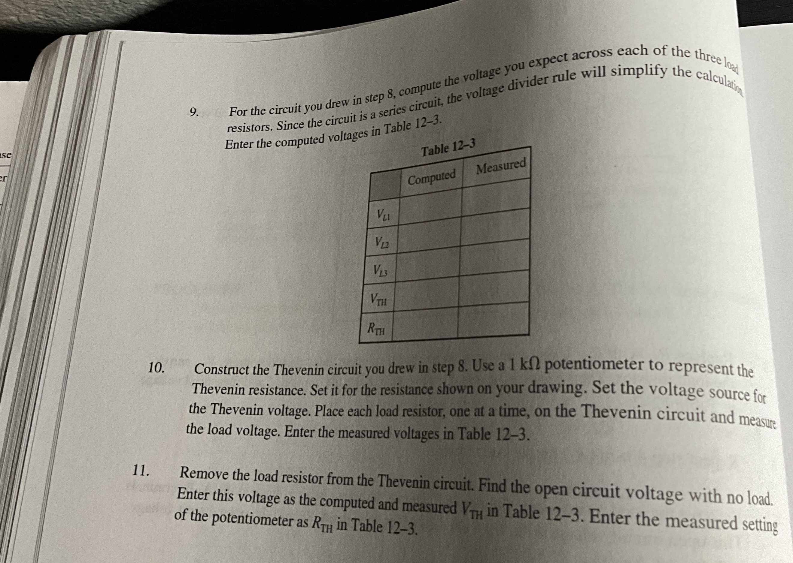
Enter the computed voltages in Table
tableComputed,Measured
Construct the Thevenin circuit you drew in step Use a potentiometer to represent the Thevenin resistance. Set it for the resistance shown on your drawing. Set the voltage source for the Thevenin voltage. Place each load resistor, one at a time, on the Thevenin circuit and measure the load voltage. Enter the measured voltages in Table
Remove the load resistor from the Thevenin circuit. Find the open circuit voltage with no load. Enter this voltage as the computed and measured in Table Enter the measured setting of the potentiometer as in Table
Step by Step Solution
There are 3 Steps involved in it
1 Expert Approved Answer
Step: 1 Unlock

Question Has Been Solved by an Expert!
Get step-by-step solutions from verified subject matter experts
Step: 2 Unlock
Step: 3 Unlock