

Question: MIPSzy_processor_example.vl module MIPSzy(clk, rst); input clk, rst; // Ctrl wires wire rf_wd_s, rf_wa_s, rf_we, rf_r1e, rf_r2e; wire add2_s; wire dm_we, dm_re; // PC wires wire
MIPSzy_processor_example.vl
module MIPSzy(clk, rst); input clk, rst; // Ctrl wires wire rf_wd_s, rf_wa_s, rf_we, rf_r1e, rf_r2e; wire add2_s; wire dm_we, dm_re; // PC wires wire [31:0] pc_out, pc_inc4; // IM/IR wires wire [31:0] ir; wire [5:0] ir31_26, ir5_0; wire [4:0] ir20_16, ir15_11, ir25_21; wire [15:0] ir15_0; // SW wires wire [31:0] ir15_0_se; // RF wires wire [4:0] rf_wa; wire [31:0] rf_wd; wire [31:0] rf_r1d, rf_r2d; // Adder wires wire [31:0] add2, add1, add_sum; // DM wires wire [31:0] dm_a; wire [31:0] dm_wd; wire [31:0] dm_rd;
// internal connections assign dm_a = rf_r1d; assign dm_wd = rf_r2d; assign add1 = rf_r1d; assign ir31_26 = ir[31:26]; assign ir5_0 = ir[5:0]; assign ir20_16 = ir[20:16]; assign ir15_11 = ir[15:11]; assign ir25_21 = ir[25:21]; assign ir15_0 = ir[15:0]; // Component instantiations mipszy_ctrl CTRL(ir31_26, ir5_0, rf_wd_s, rf_wa_s, rf_we, rf_r1e, rf_r2e, add2_s, dm_we, dm_re); register_32 PC(clk, rst, 1, pc_inc4, pc_out); inc4_32 PC_inc(pc_out, pc_inc4); mux2x1_32 RF_wd_mux(add_sum, dm_rd, rf_wd_s, rf_wd); mux2x1_5 RF_wa_mux(ir20_16, ir15_11, rf_wa_s, rf_wa); regfile_32x32 RF(clk, rst, ir25_21, rf_r1d, rf_r1e, ir20_16, rf_r2d, rf_r2e, rf_wa, rf_wd, rf_we); signext_16_32 SE(ir15_0, ir15_0_se); mux2x1_32 ADD_mux(rf_r2d, ir15_0_se, add2_s, add2); adder_32 ADD(add1, add2, add_sum); mem_1024x32 IM(clk, pc_out[11:2], ir, 1, 0, 0, 0); mem_1024x32 DM(clk, dm_a[11:2], dm_rd, dm_re, dm_a[11:2], dm_wd, dm_we); endmodule
module mipszy_ctrl(ir31_26, ir5_0, rf_wd_s, rf_wa_s, rf_we, rf_r1e, rf_r2e, add2_s, dm_we, dm_re);
input [5:0] ir31_26, ir5_0; output reg rf_wd_s, rf_wa_s, rf_we, rf_r1e, rf_r2e; output reg add2_s; output reg dm_we, dm_re;
always @* begin if (ir31_26 == 'b100011) begin // lw rf_wd_s = 0; rf_wa_s = 1; rf_we = 1; rf_r1e = 1; rf_r2e = 0; add2_s = 0; dm_we = 0; dm_re = 1; end else if (ir31_26 == 'b101011) begin // sw rf_wd_s = 0; rf_wa_s = 0; rf_we = 0; rf_r1e = 1; rf_r2e = 1; add2_s = 0; dm_we = 1; dm_re = 0; end else if (ir31_26 == 'b001000) begin // addi rf_wd_s = 1; rf_wa_s = 1; rf_we = 1; rf_r1e = 1; rf_r2e = 0; add2_s = 0; dm_we = 0; dm_re = 0; end else if (ir31_26 == 'b000000 && ir5_0 == 'b100000) begin // add rf_wd_s = 1; rf_wa_s = 0; rf_we = 1; rf_r1e = 1; rf_r2e = 1; add2_s = 1; dm_we = 0; dm_re = 0; end else begin rf_wd_s = 0; rf_wa_s = 0; rf_we = 0; rf_r1e = 0; rf_r2e = 0; add2_s = 0; dm_we = 0; dm_re = 0; end end endmodule
module register_32(clk, rst, ld, D, Q); input clk, rst; input ld; input [31:0] D; output reg [31:0] Q;
always @(posedge clk) begin if (rst) begin Q = 0; end else if (ld) begin Q = D; end end endmodule
module mem_1024x32(clk, ra, rd, re, wa, wd, we); input clk; input [9:0] ra, wa; input re, we; output reg [31:0] rd; input [31:0] wd; reg [31:0] memory [0:1023]; always @(posedge clk) begin if (we) begin memory[wa] = wd; end end always @* begin if (re) begin rd = memory[ra]; end else begin rd = 0; end end endmodule
module regfile_32x32(clk, rst, r1a, r1d, r1e, r2a, r2d, r2e, wa, wd, we); input clk, rst; input [4:0] r1a, r2a, wa; input r1e, r2e, we; output reg [31:0] r1d, r2d; input [31:0] wd;
integer i; reg [31:0] registers [0:31]; // Write procedure always @(posedge clk) begin if (rst) begin for (i = 0; i
// Read port 2 if (r2e) begin r2d = registers[r2a]; end else begin r2d = 0; end end endmodule
module adder_32(A, B, S); input [31:0] A, B; output reg [31:0] S;
always @(A, B) begin S = A + B; end endmodule
module inc4_32(A, S); input [31:0] A; output reg [31:0] S;
always @(A) begin S = A + 4; end endmodule
module mux2x1_32(I1, I0, s, D); input [31:0] I1, I0; input s; output reg [31:0] D; always @(I1, I0, s) begin if (!s) begin D = I0; end else begin D = I1; end end endmodule
module mux2x1_5(I1, I0, s, D); input [4:0] I1, I0; input s; output reg [4:0] D; always @(I1, I0, s) begin if (!s) begin D = I0; end else begin D = I1; end end endmodule
module signext_16_32(I, O); input signed [15:0] I; output reg [31:0] O;
always @(I) begin O = I; end endmodule
module main; reg clk_tb, rst_tb; localparam CLK_PERIOD = 20; MIPSzy MIPSzy_0(clk_tb, rst_tb); initial begin $monitor("Time = %0t Clk = %0d Mem = %0d", $time, clk_tb, MIPSzy_0.DM.memory[(5000-4096)/4]); // initialize instruction memory MIPSzy_0.IM.memory[0] = 'b00100000000011100001001110001000; // addi $t6, $zero, 5000 MIPSzy_0.IM.memory[1] = 'b10001101110010000000000000000000; // lw $t0, 0($t6) # Load from DM[5000] MIPSzy_0.IM.memory[2] = 'b00000001000010000100100000100000; // add $t1, $t0, $t0 # Double the values MIPSzy_0.IM.memory[3] = 'b10101101110010010000000000000000; // sw $t1, 0($t6) # Store to DM[5000]
MIPSzy_0.DM.memory[(5000-4096)/4] = 10; end
// Generate clock always begin clk_tb = 0; #(CLK_PERIOD / 2); clk_tb = 1; #(CLK_PERIOD / 2); end initial begin rst_tb = 1; #CLK_PERIOD rst_tb = 0; #100 $finish; end endmodule
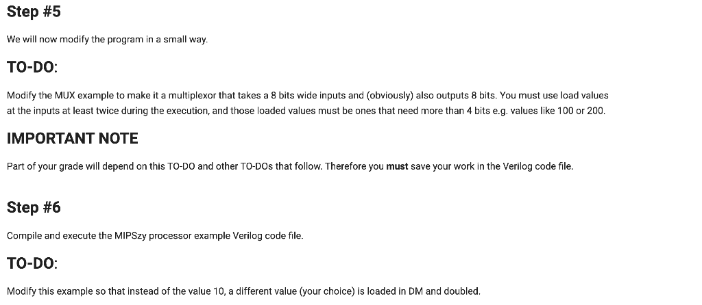
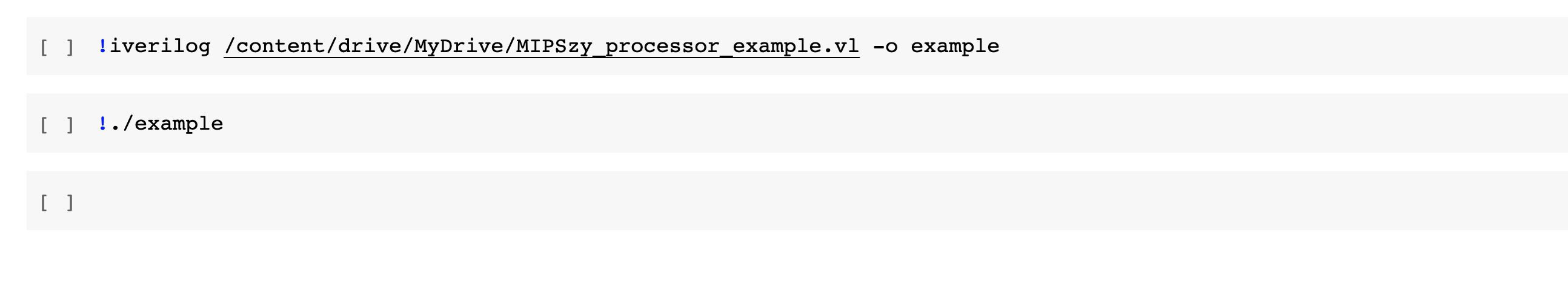
Step #5 We will now modify the program in a small way. TO-DO: Modify the MUX example to make it a multiplexor that takes a 8 bits wide inputs and obviously) also outputs 8 bits. You must use load values at the inputs at least twice during the execution, and those loaded values must be ones that need more than 4 bits e.g. values like 100 or 200. IMPORTANT NOTE Part of your grade will depend on this TO-DO and other TO-DOs that follow. Therefore you must save your work in the Verilog code file. Step #6 Compile and execute the MIPSzy processor example Verilog code file. TO-DO: Modify this example so that instead of the value 10, a different value (your choice) is loaded in DM and doubled. Step #5 We will now modify the program in a small way. TO-DO: Modify the MUX example to make it a multiplexor that takes a 8 bits wide inputs and obviously) also outputs 8 bits. You must use load values at the inputs at least twice during the execution, and those loaded values must be ones that need more than 4 bits e.g. values like 100 or 200. IMPORTANT NOTE Part of your grade will depend on this TO-DO and other TO-DOs that follow. Therefore you must save your work in the Verilog code file. Step #6 Compile and execute the MIPSzy processor example Verilog code file. TO-DO: Modify this example so that instead of the value 10, a different value (your choice) is loaded in DM and doubled
Step by Step Solution
There are 3 Steps involved in it

Get step-by-step solutions from verified subject matter experts