

Question: module test (input in, clk, output reg out) reg qi, q2i E always(posedge clk) begin qi in; out q2: end endmodule q 1 q2 out-reg0
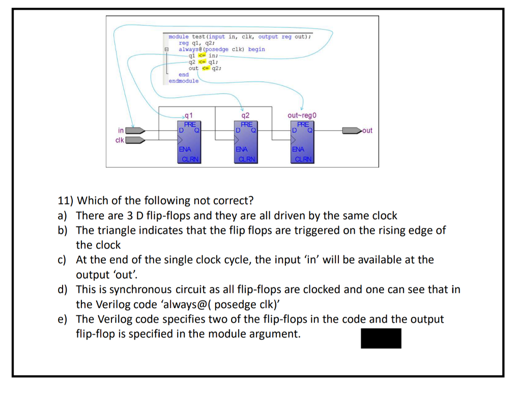
module test (input in, clk, output reg out) reg qi, q2i E always(posedge clk) begin qi in; out q2: end endmodule q 1 q2 out-reg0 D Q D Q D Q ut in clk 11) Which of the following not correct? a) There are 3 D flip-flops and they are all driven by the same clock b) The triangle indicates that the flip flops are triggered on the rising edge of c) At the end of the single clock cycle, the input 'in' will be available at the d) This is synchronous circuit as all flip-flops are clocked and one can see that in e) The Verilog code specifies two of the flip-flops in the code and the output the clock output 'out'. the Verilog code 'always@( posedge clk)' flip-flop is specified in the module argument
Step by Step Solution
There are 3 Steps involved in it

Get step-by-step solutions from verified subject matter experts