

Question: Multiply and Add: Design a combinational circuit that computes P = XY + Q +R The inputs X and Y are 4-bit unsigned integers. The
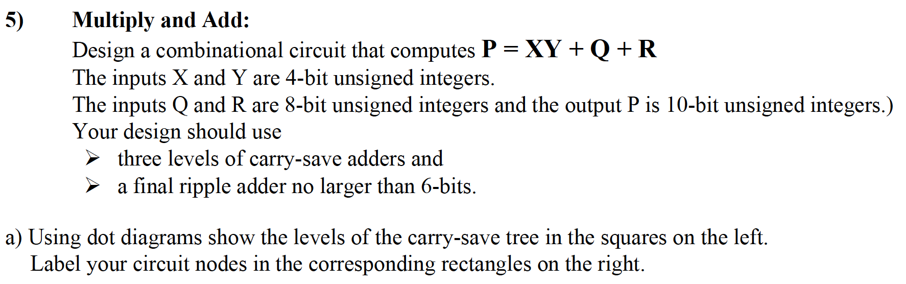

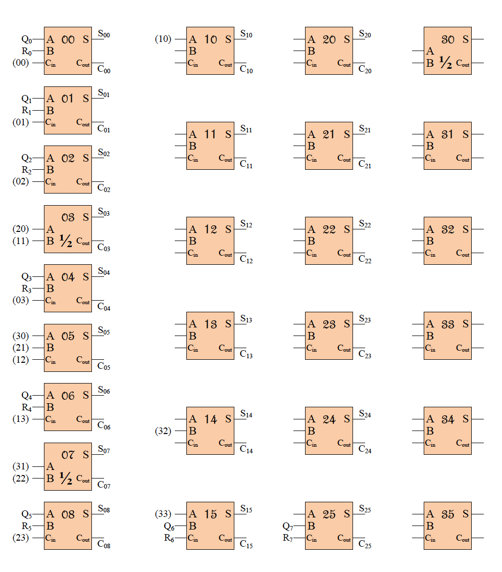
Multiply and Add: Design a combinational circuit that computes P = XY + Q +R The inputs X and Y are 4-bit unsigned integers. The inputs Q and R are 8-bit unsigned integers and the output P is 10-bit unsigned integers.) Your design should use three levels of carry-save adders and > a final ripple adder no larger than 6-bits. a) Using dot diagrams show the levels of the carry-save tree in the squares on the left. Label your circuit nodes in the corresponding rectangles on the right. b) Connect the adders. You do not need to draw the AND gates, simply label the nodes using the notation given above. Label the output bits, Pi. Indicate half adders by writing 1/2 in the box. - A 00 SS -A 20 5 520 20 RGB HA 30 s -B 1/2 Cou (00) Cin Cout Coo Co a A oi s RGB (01) CO Couto A 11 S CM HA 21 s S21 HA 31 s Cin Cout Cout Cout C21 A o2 st R2-B (02) C Couti 03 s S03 (20) A HA 22 s S2 LA 12 s $12 A 32 S (11) B 12 Couro Cou Cou 03-A 04 s S04 R3-B (03) Coutcome 13 S CM -A 23 s S23 -B (30)A 05 s Sos (12) C Cont con CM -A 33 SH Ci Cout (21) - B Cin Cout C3 Q4A 06 s RGB (13) & Count Coo HA 14 S S14 GA 24 s $24 A 34 sh (32) B Cout C14 (31) (22) A B 12 Cout -A 35 s 6-A 08 s Sos Rs-B (23) Court os (33) A 15 s Sis 06-B Roa Cour cs A Q-B R C 25 s S25 Cout cas Multiply and Add: Design a combinational circuit that computes P = XY + Q +R The inputs X and Y are 4-bit unsigned integers. The inputs Q and R are 8-bit unsigned integers and the output P is 10-bit unsigned integers.) Your design should use three levels of carry-save adders and > a final ripple adder no larger than 6-bits. a) Using dot diagrams show the levels of the carry-save tree in the squares on the left. Label your circuit nodes in the corresponding rectangles on the right. b) Connect the adders. You do not need to draw the AND gates, simply label the nodes using the notation given above. Label the output bits, Pi. Indicate half adders by writing 1/2 in the box. - A 00 SS -A 20 5 520 20 RGB HA 30 s -B 1/2 Cou (00) Cin Cout Coo Co a A oi s RGB (01) CO Couto A 11 S CM HA 21 s S21 HA 31 s Cin Cout Cout Cout C21 A o2 st R2-B (02) C Couti 03 s S03 (20) A HA 22 s S2 LA 12 s $12 A 32 S (11) B 12 Couro Cou Cou 03-A 04 s S04 R3-B (03) Coutcome 13 S CM -A 23 s S23 -B (30)A 05 s Sos (12) C Cont con CM -A 33 SH Ci Cout (21) - B Cin Cout C3 Q4A 06 s RGB (13) & Count Coo HA 14 S S14 GA 24 s $24 A 34 sh (32) B Cout C14 (31) (22) A B 12 Cout -A 35 s 6-A 08 s Sos Rs-B (23) Court os (33) A 15 s Sis 06-B Roa Cour cs A Q-B R C 25 s S25 Cout cas
Step by Step Solution
There are 3 Steps involved in it

Get step-by-step solutions from verified subject matter experts