

Question: Name 3. From the slides and the reference materials, we see that there are two methods for implementing logic in Verilog HDL. The circuit can
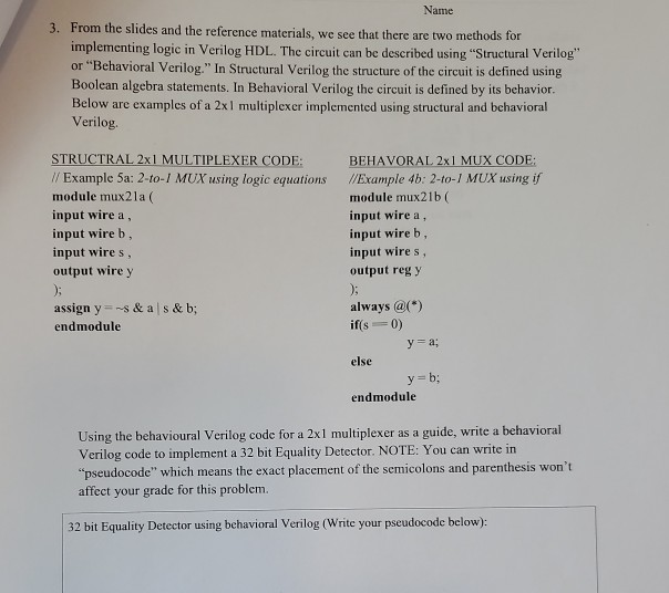
Name 3. From the slides and the reference materials, we see that there are two methods for implementing logic in Verilog HDL. The circuit can be described using "Structural Verilog or "Behavioral Verilog." In Structural Verilog the structure of the circuit is defined using Boolean algebra statements. In Behavioral Verilog the circuit is defined by its behavior. Below are examples of a 2x1 multiplexer implemented using structural and behavioral Verilog. STRUCTRAL 2x1 MULTIPLEXER CODE: // Example 5a: 2-to-/ MUX using logic equations module mux21a ( input wire a, input wireb, input wires, output wire y BEHAVORAL 2x1 MUX CODE: //Example 4b: 2-to-/ MUX using if module mux21b input wire a, input wireb, input wires, output reg y assign y=s& als & b; endmodule always @) if(s ==0) y=a; else y=b: endmodule Using the behavioural Verilog code for a 2x1 multiplexer as a guide, write a behavioral Verilog code to implement a 32 bit Equality Detector. NOTE: You can write in "pseudocode" which means the exact placement of the semicolons and parenthesis won't affect your grade for this problem 32 bit Equality Detector using behavioral Verilog (Write your pseudocode below) Name 3. From the slides and the reference materials, we see that there are two methods for implementing logic in Verilog HDL. The circuit can be described using "Structural Verilog or "Behavioral Verilog." In Structural Verilog the structure of the circuit is defined using Boolean algebra statements. In Behavioral Verilog the circuit is defined by its behavior. Below are examples of a 2x1 multiplexer implemented using structural and behavioral Verilog. STRUCTRAL 2x1 MULTIPLEXER CODE: // Example 5a: 2-to-/ MUX using logic equations module mux21a ( input wire a, input wireb, input wires, output wire y BEHAVORAL 2x1 MUX CODE: //Example 4b: 2-to-/ MUX using if module mux21b input wire a, input wireb, input wires, output reg y assign y=s& als & b; endmodule always @) if(s ==0) y=a; else y=b: endmodule Using the behavioural Verilog code for a 2x1 multiplexer as a guide, write a behavioral Verilog code to implement a 32 bit Equality Detector. NOTE: You can write in "pseudocode" which means the exact placement of the semicolons and parenthesis won't affect your grade for this problem 32 bit Equality Detector using behavioral Verilog (Write your pseudocode below)
Step by Step Solution
There are 3 Steps involved in it

Get step-by-step solutions from verified subject matter experts