

Question: ncount2.tcl: #********************************************************************** # ncount2 #********************************************************************** #Lab5 # #********************************************************************** # to run this # putverilog files and lab3.scl into a folder , eg ~/cnt-seq # cd
ncount2.tcl:
#********************************************************************** # ncount2 #********************************************************************** #Lab5 # #********************************************************************** # to run this # putverilog files and lab3.scl into a folder , eg ~/cnt-seq # cd ~/cnt-seq # dc_shell # enter each uncommented command listed below # or to run all of these do the following at teh dc_shell prompt # source cnt-seq.scr #********************************************************************** # # # First, set up the path to the libraries. To use a different # technology library, these variables may be changed. # # (no need as these are already set in .synopsis_dc.setup ) #********************************************************************** #search_path = { ., synopsys_root + /libraries/syn} #target_library = {class.db} #symbol_library = {class.sdb} #link_path = {class.db} #********************************************************************** # # The read command is used to read in the Verilog source file. # # The read command is described in the Design Compiler Command # Reference Manual. # #******************************************************************* read_verilog {ncount2.v ncount.v debounce.v slow_strobe.v} #read_verilog display_digit.v #read_verilog display_value.v #read_verilog tim.v #read_verilog clock.v link list_designs -show_file printvar current_design check_design # now set create clock spec # There are many other clock properties that could be set eg # set_clock_latency # set_propagated_clock # set_clock_uncertainty # set_clock_transition create_clock clk -period 20 # set opererating condition worst cse, typical or best case #set_operating_conditions WCCOM # set drive strength on signals connected to inputs
set_drive 1 [all_inputs] # set drive strength on signals connected to outputs set_load 2 [all_outputs] # set max allowable delays set_input_delay -max 2 -clock clk [all_inputs ] set_output_delay -max 2 -clock clk [all_outputs] set auto_wire_load_selection true # set max area allowed max_area 200 # this compiles (synthesizes) the verilog file compile # if compile procedes with no errors then create reports report -area > ncount2_area_report.txt report -timing > ncount2_timing_report.txt # write netlist files for simulation and for layout change_names -rules verilog -hierarchy write_file -format verilog -hierarchy -output "ncount2_net.v" write_file -format ddc -hierarchy -output "ncount2_net.ddc" write_sdf "ncount2.sdf" check_design #write_parasitics -output parasitics_file_name #write_sdc sdc_file_name #write_floorplan -all phys_cstr_file_name.tcl #to get out of dc_shell
// Header
`define N 8 // N-bit counter
module n_count (
input clk,
input reset_n,
input on_off,
input up_down,
output reg [`N-1:0] count
);
// Internal variables
reg [`N-1:0] next_count;
// Counter logic
always @(posedge clk) begin
if (~reset_n)
count
else if (on_off)
count
end
always @* begin
if (up_down)
next_count = count == 2**`N-1`-1 ? 0 : count + 1;
else
next_count = count == 0 ? 2**`N-1`-1 : count - 1;
end
endmodule
`define N 8 // N-bit counter
module ncount_tb;
// Inputs
reg clk;
reg reset_n;
reg on_off;
reg up_down;
// Outputs
wire [`N-1:0] count;
// Instantiate the n-bit counter
n_count nc (
.clk(clk),
.reset_n(reset_n),
.on_off(on_off),
.up_down(up_down),
.count(count)
);
// Clock generator
always #50 clk = ~clk;
// Reset sequence
initial begin
reset_n = 1'b0;
#100 reset_n = 1'b1;
end
// Sequence for up/down and on/off
initial begin
on_off = 1'b0;
#200 on_off = 1'b1;
#100 up_down = 1'b0;
#100 up_down = 1'b1;
end
// Display or monitor to see all inputs and outputs
initial begin
$sdisplay("Time, clk, reset_n, on_off, up_down, count");
$monitor("%g, %b, %b, %b, %b, %b", $time, clk, reset_n, on_off, up_down, count);
end
endmodule
This is a test bench for the N-bit counter n_count. It includes initial statements to enable SystemVerilog $sdisplay and $monitor commands, which display and monitor the values of the inputs and outputs, respectively. The test bench also includes a clock generator with a period of 100 ns, a reset sequence, and a sequence for the on_off and up_down inputs. The N-bit counter is instantiated within the test bench, and the inputs and outputs are connected to the corresponding signals in the test bench.
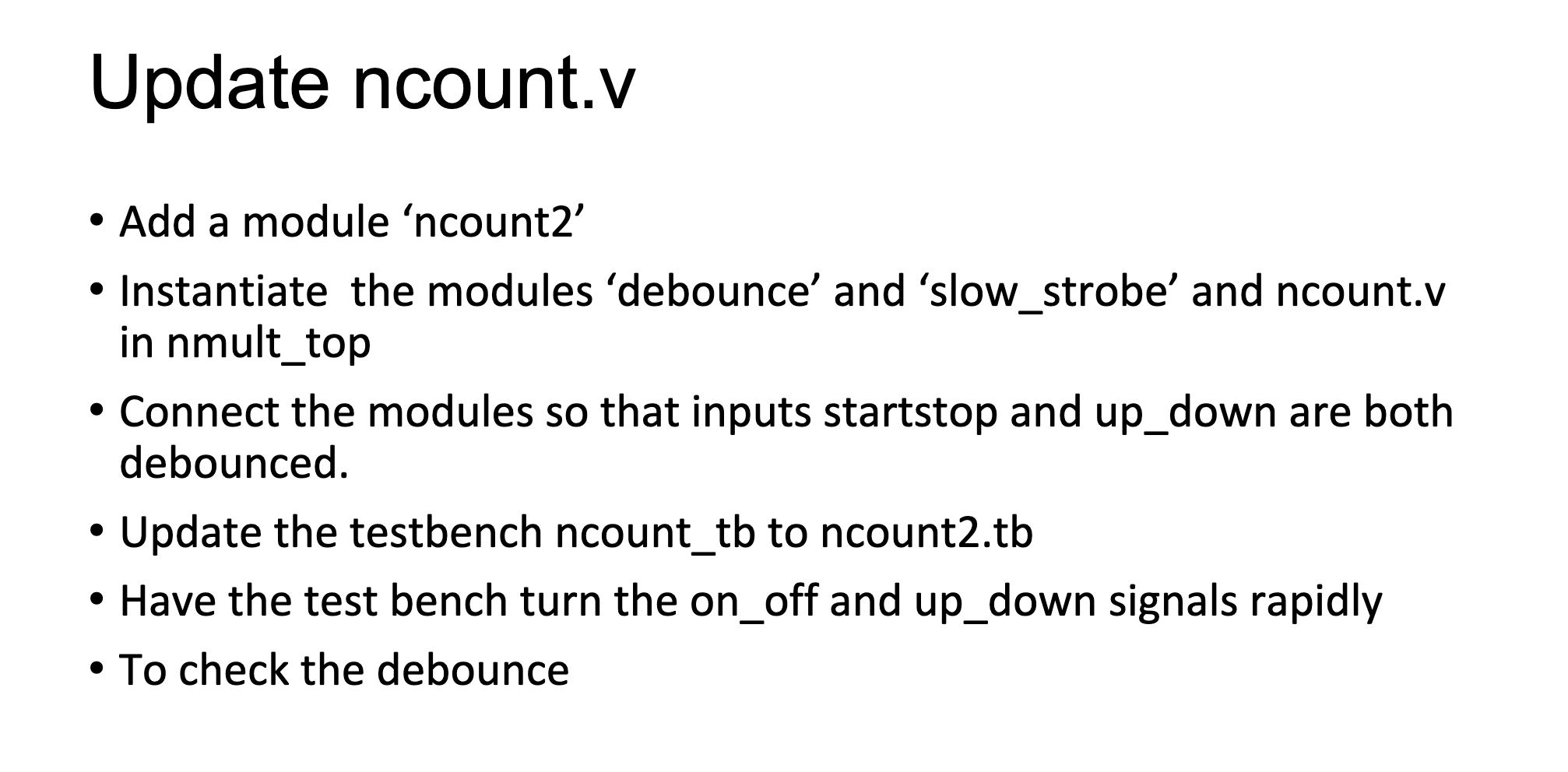
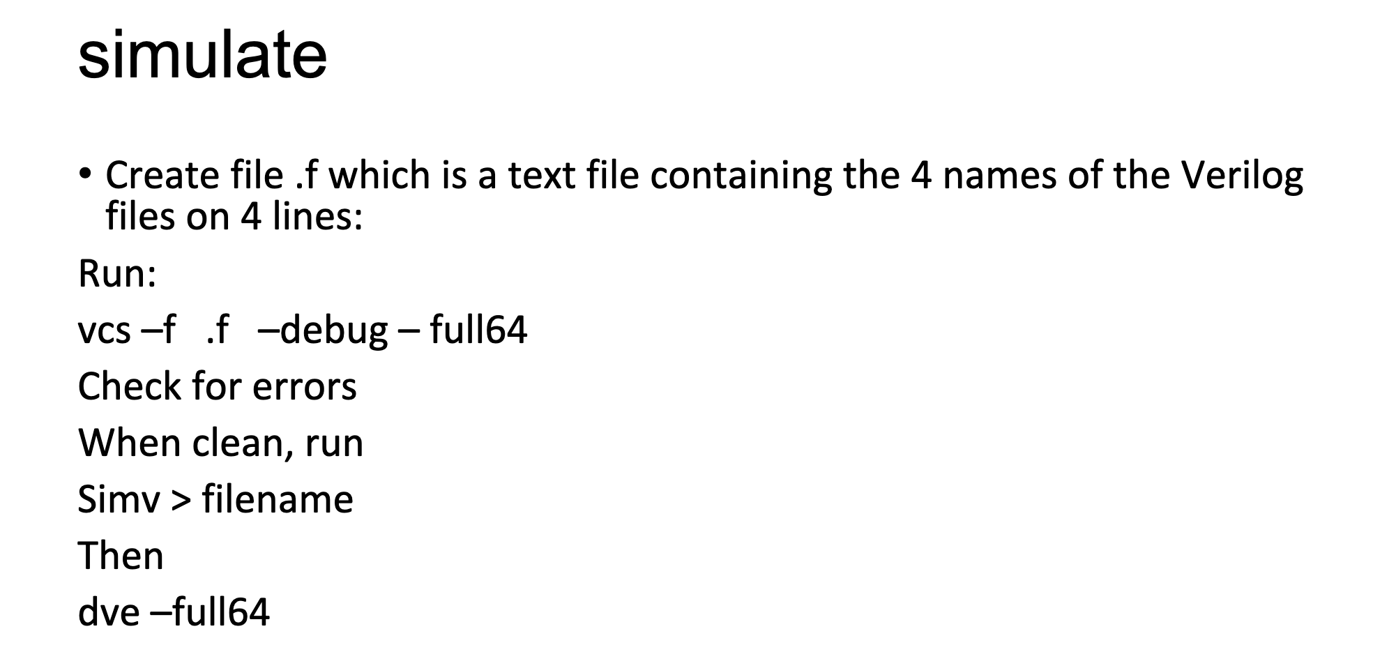
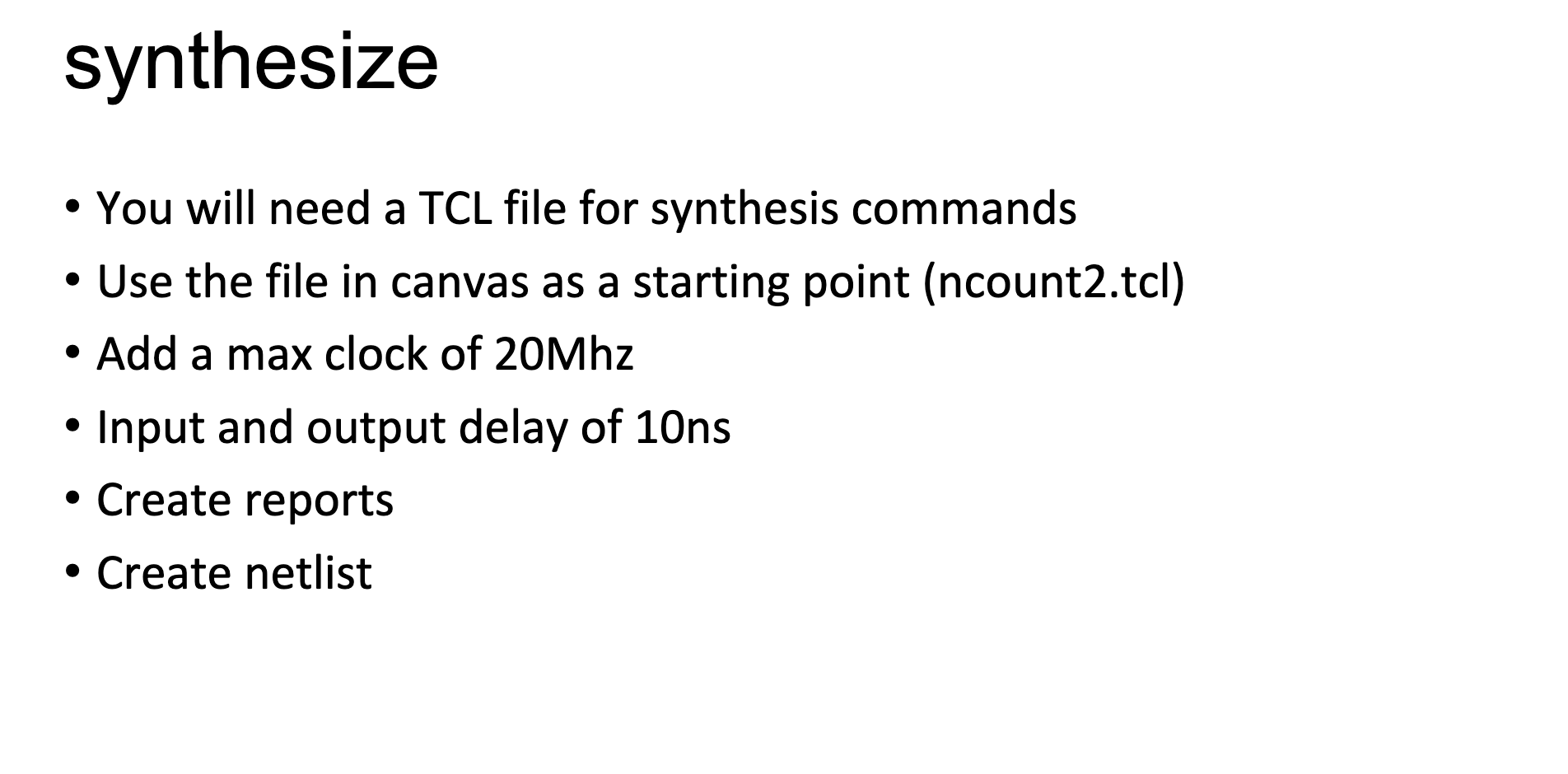
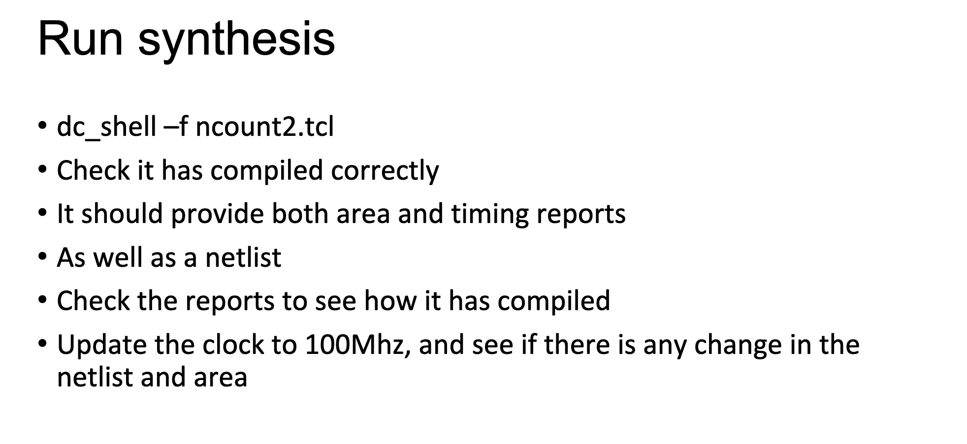
Update ncount.v - Add a module 'ncount2' - Instantiate the modules 'debounce' and 'slow_strobe' and ncount.v in nmult_top - Connect the modules so that inputs startstop and up_down are both debounced. - Update the testbench ncount_tb to ncount2.tb - Have the test bench turn the on_off and up_down signals rapidly - To check the debounce simulate - Create file .f which is a text file containing the 4 names of the Verilog files on 4 lines: Run: vcs -f .f -debug - full64 Check for errors When clean, run Simv > filename Then dve-full64 synthesize - You will need a TCL file for synthesis commands - Use the file in canvas as a starting point (ncount2.tcl) - Add a max clock of 20Mhz - Input and output delay of 10ns - Create reports - Create netlist Run synthesis - dc_shell-f ncount2.tcl - Check it has compiled correctly - It should provide both area and timing reports - As well as a netlist - Check the reports to see how it has compiled - Update the clock to 100Mhz, and see if there is any change in the netlist and area
Step by Step Solution
There are 3 Steps involved in it

Get step-by-step solutions from verified subject matter experts