

Question: Need complete answer and solution in multisim Instruction: Solve the question by calculation. Then prove the calculated results using MULTISIM. Include MULTISIM screen shots in
Need complete answer and solution in multisim
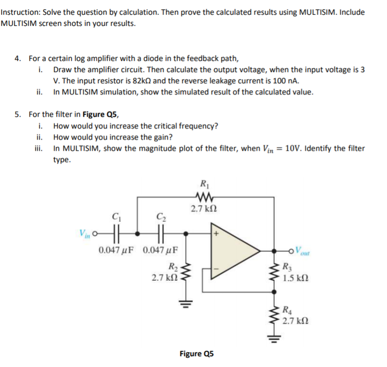
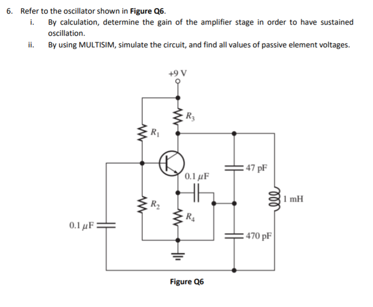
Instruction: Solve the question by calculation. Then prove the calculated results using MULTISIM. Include MULTISIM screen shots in your results. 4. For a certain log amplifier with a diode in the feedback path, i. Draw the amplifier circuit. Then calculate the output voltage, when the input voltage is 3 V. The input resistor is 82k1 and the reverse leakage current is 100 nA. ii. In MULTISIM simulation, show the simulated result of the calculated value. 5. For the filter in Figure 25, i. How would you increase the critical frequency? ii. How would you increase the gain? ili. In MULTISIM, show the magnitude plot of the filter, when Vin = 10V. Identify the filter type. Ri w 2.7 k12 in C C2 11 0.047 uF 0.047 uF R2 2.7k12 R3 1.5 k2 WI R4 2.7k 2 Figure 25 6. Refer to the oscillator shown in Figure 26. i. By calculation, determine the gain of the amplifier stage in order to have sustained oscillation. ii. By using MULTISIM, simulate the circuit, and find all values of passive element voltages. +9V R3 RI w :47 pF 0.1 uF 1 mH R2 w R4 0.1 uF 470 pF = Figure Q6 Instruction: Solve the question by calculation. Then prove the calculated results using MULTISIM. Include MULTISIM screen shots in your results. 4. For a certain log amplifier with a diode in the feedback path, i. Draw the amplifier circuit. Then calculate the output voltage, when the input voltage is 3 V. The input resistor is 82k1 and the reverse leakage current is 100 nA. ii. In MULTISIM simulation, show the simulated result of the calculated value. 5. For the filter in Figure 25, i. How would you increase the critical frequency? ii. How would you increase the gain? ili. In MULTISIM, show the magnitude plot of the filter, when Vin = 10V. Identify the filter type. Ri w 2.7 k12 in C C2 11 0.047 uF 0.047 uF R2 2.7k12 R3 1.5 k2 WI R4 2.7k 2 Figure 25 6. Refer to the oscillator shown in Figure 26. i. By calculation, determine the gain of the amplifier stage in order to have sustained oscillation. ii. By using MULTISIM, simulate the circuit, and find all values of passive element voltages. +9V R3 RI w :47 pF 0.1 uF 1 mH R2 w R4 0.1 uF 470 pF = Figure Q6
Step by Step Solution
There are 3 Steps involved in it

Get step-by-step solutions from verified subject matter experts