

Question: Need help in logic design. Please fill out the table. Control Circuit Truth Table: (The initial state of the machine is filled out as an
Need help in logic design. Please fill out the table.
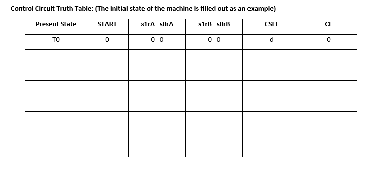
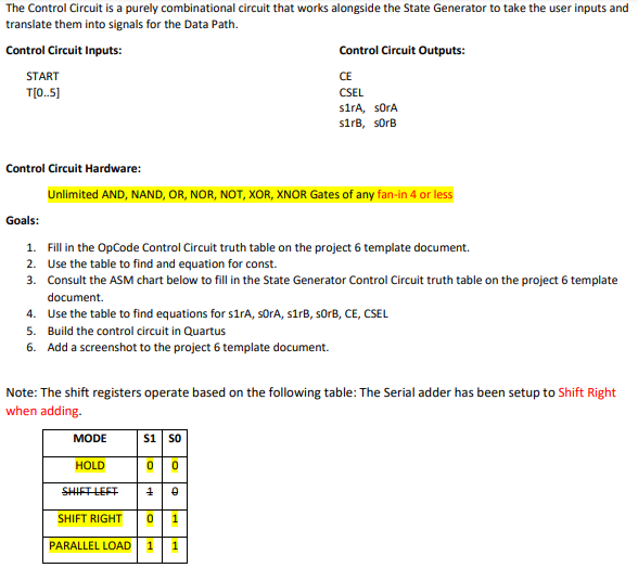
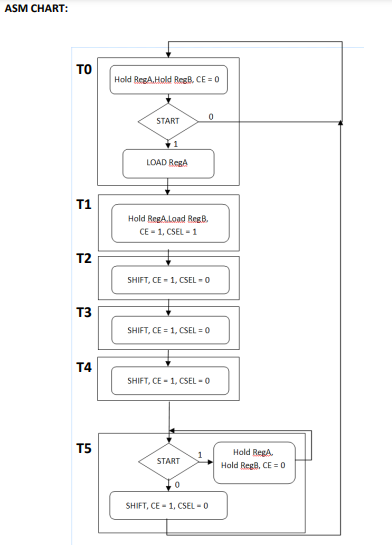
Control Circuit Truth Table: (The initial state of the machine is filled out as an example) The Control Circuit is a purely combinational circuit that works alongside the State Generator to take the user inputs and translate them into signals for the Data Path. is: Control Circuit Hardware: Unlimited AND, NAND, OR, NOR, NOT, XOR, XNOR Gates of any fan-in 4 or less Goals: 1. Fill in the OpCode Control Circuit truth table on the project 6 template document. 2. Use the table to find and equation for const. 3. Consult the ASM chart below to fill in the State Generator Control Circuit truth table on the project 6 template document. 4. Use the table to find equations for $1 rA, sOrA, s1rB, sOrB, CE, CSEL 5. Build the control circuit in Quartus 6. Add a screenshot to the project 6 template document. Note: The shift registers operate based on the following table: The Serial adder has been setup to Shift Right when adding. ASM CHART
Step by Step Solution
There are 3 Steps involved in it

Get step-by-step solutions from verified subject matter experts