

Question: Need help on this question will give good review! Link to circuit for this question is http://i.imgur.com/7Ecb2Lw.png 1) The floating point to be used in
Need help on this question will give good review!
Link to circuit for this question is http://i.imgur.com/7Ecb2Lw.png
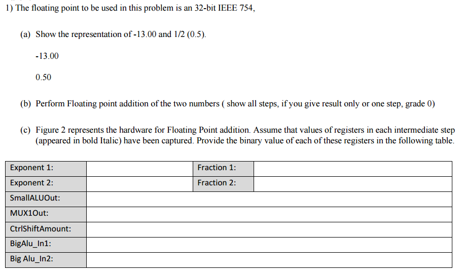
1) The floating point to be used in this problem is an 32-bit IEEE 754, (a) Show the representation of -13.00 and 112 (0.5) 13.00 0.50 (b) Perform Floating point addition of the two numbers show all steps, if you give result only or one step, grade 0) (c) Figure 2 represents the hardware for Floating Point addition. Assume that values of registers in each intermediate step (appeared in bold Italic) have been captured. Provide the binary value of each of these registers in the following table Exponent 1: Fraction 1: Fraction 2: Exponent 2 SmallALU Out: MUX1Out: Ctrl ShiftAmount: BigAlu In1: Big Alu In2: 1) The floating point to be used in this problem is an 32-bit IEEE 754, (a) Show the representation of -13.00 and 112 (0.5) 13.00 0.50 (b) Perform Floating point addition of the two numbers show all steps, if you give result only or one step, grade 0) (c) Figure 2 represents the hardware for Floating Point addition. Assume that values of registers in each intermediate step (appeared in bold Italic) have been captured. Provide the binary value of each of these registers in the following table Exponent 1: Fraction 1: Fraction 2: Exponent 2 SmallALU Out: MUX1Out: Ctrl ShiftAmount: BigAlu In1: Big Alu In2
Step by Step Solution
There are 3 Steps involved in it

Get step-by-step solutions from verified subject matter experts