

Question: Need help to design 3 to 7 binary-to-thermometer converter circuit please provide the answer with details and don't summarize the assignment and post it as
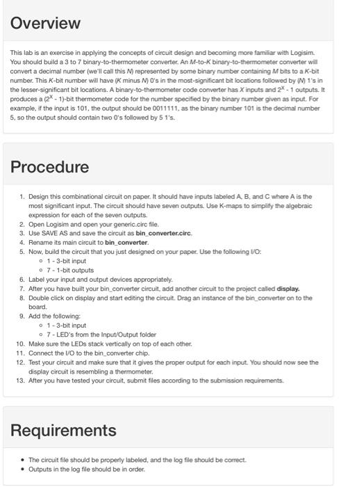
This lab is an exercise in applying the concepts of circuit design and becoming more familiar with Logisim. You should build a 3 to 7 binary-to-thermometer converter. An M-to-K binary-to-thermometer converter will corvert a decimal number (we'll call this N ) represented by some binary number containing M bits to a K-bit number. This K-bit number will have (K minus N)O 's in the most-significant bit locations followed by (M)1 's in the lesser-significant bit locations. A binary-to-thermometer code converter has X inputs and 2X - 1 outputs. it produces a (2x1)-bit thermometer code for the number specified by the binary number given as input. For example, if the input is 101, the output should be 0011111 , as the binary number 101 is the decimal number 5, so the output should contain two 0's followed by 5 1's. Procedure 1. Design this combinational circuit on paper. It should have inputs labeled A,B, and C where A is the most significant input. The circuit should have seven outputs, Use K-maps to simplify the algebraic expression for each of the seven outputs. 2. Open Logisim and open your generic.circ file. 3. Use SAVE AS and save the circuit as bin_converter.circ. 4. Rename its main circuit to bin_converter. 5. Now, build the circuit that you just designed on your paper. Use the following VO: 0 - 3-bit input - 7 - 1-bit outputs 6. Label your input and output devices appropriately. 7. After you have built your bin converter circuit, add another circuit to the project caled display. 8. Double click on display and start editing the circuit. Drag an instance of the bin_converter on to the board. 9. Add the following: - 1-3-bit input - 7 -LED's from the Input/Output folder 10. Make sure the LEDs stack vertically on top of each other. 11. Connect the MO to the bin_converter chip. 12. Test your circuit and make sure that it gives the proper output for each input. You should now see the display circuit is resembling a thermometer. 13. After you have tested your circuit, submit files according to the submission requirements. Requirements - The circuit file should be properly labeled, and the log file should be correct. - Outputs in the log file should be in order
Step by Step Solution
There are 3 Steps involved in it

Get step-by-step solutions from verified subject matter experts