

Question: NEED HELP WITH MATLAB 3. (5 points) The circuit shown below is an RL circuit: O Vin Vout If we apply a sinusoidal input voltage,
 NEED HELP WITH MATLAB
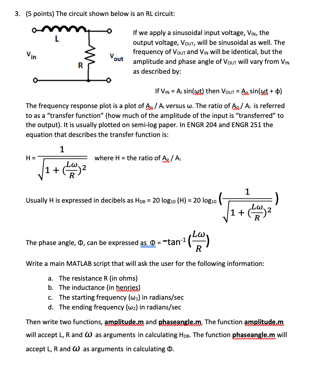
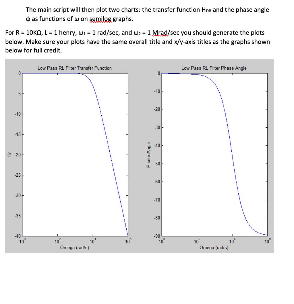
3. (5 points) The circuit shown below is an RL circuit: O Vin Vout If we apply a sinusoidal input voltage, Vin, the output voltage, Vout, will be sinusoidal as well. The frequency of Vous and Vin will be identical, but the amplitude and phase angle of Vout will vary from Vin as described by: R If Vin = A sin(wt) then Vout = A, sin(wt + 0) The frequency response plot is a plot of Ae / Ai versus w. The ratio of A / A is referred to as a "transfer function (how much of the amplitude of the input is "transferred to the output). It is usually plotted on semi-log paper. In ENGR 204 and ENGR 251 the equation that describes the transfer function is: 1 H= where H = the ratio of A / Ai 1 + 2 1 Usually H is expressed in decibels as Hob = 20 log10 (H) = 20 log10 ) 1+ The phase angle, 0, can be expressed as 0 = -tan-1 het hy Write a main MATLAB script that will ask the user for the following information: a. The resistance R (in ohms) b. The inductance (in henries) C. The starting frequency (wa) in radians/sec d. The ending frequency (w2) in radians/sec Then write two functions, amplitude.m and phaseangle.m. The function amplitude.m will accept L, R and W as arguments in calculating Hpb. The function phaseangle.m will accept L, R and W as arguments in calculating O. The main script will then plot two charts: the transfer function Hps and the phase angle as functions of w on semilog graphs. For R = 10KS, L = 1 henry, W1 = 1 rad/sec, and W2 = 1 Mrad/sec you should generate the plots below. Make sure your plots have the same overall title and x/y-axis titles as the graphs shown below for full credit. Low Pass RL Filter Transfer Function Low Pass RL Filter Phase Angle 0 0 -10 -5 -20 -10 -30 -15 -40 -200 Angle Phase -50 -25 -60 -30 -70 -35 -80 -40 -90 10 10 10 10? 10* 102 10 Omega (rad/s) 100 Omega (rad/s) 3. (5 points) The circuit shown below is an RL circuit: O Vin Vout If we apply a sinusoidal input voltage, Vin, the output voltage, Vout, will be sinusoidal as well. The frequency of Vous and Vin will be identical, but the amplitude and phase angle of Vout will vary from Vin as described by: R If Vin = A sin(wt) then Vout = A, sin(wt + 0) The frequency response plot is a plot of Ae / Ai versus w. The ratio of A / A is referred to as a "transfer function (how much of the amplitude of the input is "transferred to the output). It is usually plotted on semi-log paper. In ENGR 204 and ENGR 251 the equation that describes the transfer function is: 1 H= where H = the ratio of A / Ai 1 + 2 1 Usually H is expressed in decibels as Hob = 20 log10 (H) = 20 log10 ) 1+ The phase angle, 0, can be expressed as 0 = -tan-1 het hy Write a main MATLAB script that will ask the user for the following information: a. The resistance R (in ohms) b. The inductance (in henries) C. The starting frequency (wa) in radians/sec d. The ending frequency (w2) in radians/sec Then write two functions, amplitude.m and phaseangle.m. The function amplitude.m will accept L, R and W as arguments in calculating Hpb. The function phaseangle.m will accept L, R and W as arguments in calculating O. The main script will then plot two charts: the transfer function Hps and the phase angle as functions of w on semilog graphs. For R = 10KS, L = 1 henry, W1 = 1 rad/sec, and W2 = 1 Mrad/sec you should generate the plots below. Make sure your plots have the same overall title and x/y-axis titles as the graphs shown below for full credit. Low Pass RL Filter Transfer Function Low Pass RL Filter Phase Angle 0 0 -10 -5 -20 -10 -30 -15 -40 -200 Angle Phase -50 -25 -60 -30 -70 -35 -80 -40 -90 10 10 10 10? 10* 102 10 Omega (rad/s) 100 Omega (rad/s)
Step by Step Solution
There are 3 Steps involved in it

Get step-by-step solutions from verified subject matter experts