

Question: No reference. Question: Image transcription text 3 Lab Assignment For the lab assignment, you are to model and simulate the system shown in Fig. 5.
No reference.
Question:
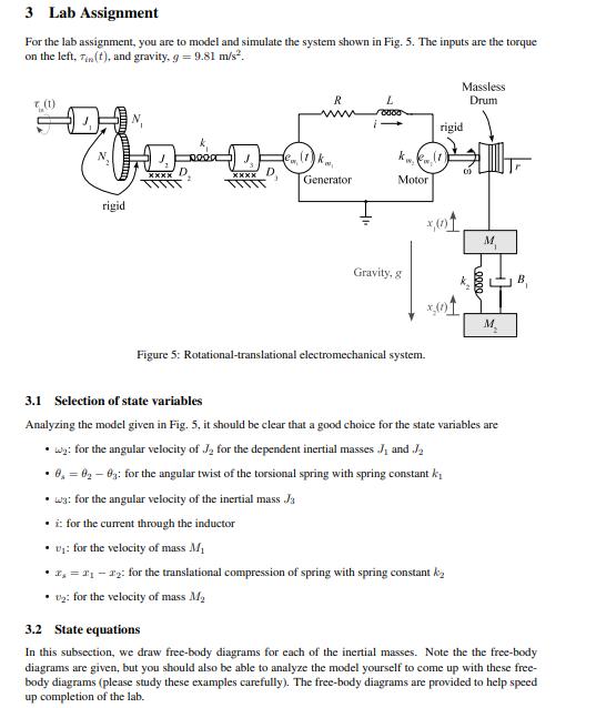
Image transcription text
3 Lab Assignment For the lab assignment, you are to model and simulate the system shown in Fig. 5.The inputs are the torque on the left, Tin (t), and gravity. g = 9.81 m/s". Massless (1) R Drum V WW
rigid N. Knee Generator Motor rigid Gravity, 8 B ^DOOO x,(OT Figure 5: Rotational-translat...
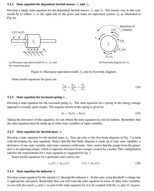
Image transcription text
3.2.1 State equation for dependent inertial masses J and J2 Develop a single state equation for thedependent inertial masses / and /2. The easiest way in this case would be to reflect J to the right-side
of the gears and make an equivalent system Je as illustrated in Fig. 64. direction of rotatio...
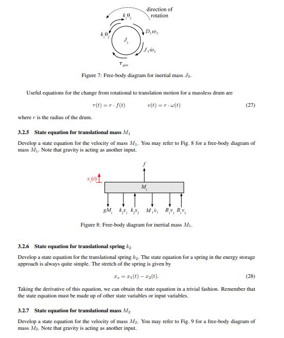
Image transcription text
direction of rotation D,w, Figure 7: Free-body diagram for inertial mass Ja. Useful equations for thechange from rotational to translation motion for a massless drum are T ( t ) = r - f(t) v(t ) = r - w(t) (27)
where r is the radius of the drum. 3.2.5 State equation for translational mass M Develop a s...
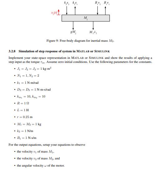
Image transcription text
BV, BV gM M.V2 Figure 9: Free-body diagram for inertial mass Me. 3.2.8 Simulation of step response ofsystem in MATLAB or SIMULINK Implement your state-space representation in MATLAB or SIMULINK
and show the results of applying a step input as the torque Tin. Assume zero initial conditi...
3 Lab Assignment For the lab assignment, you are to model and simulate the system shown in Fig. 5. The inputs are the torque on the left, Ti(t), and gravity, g = 9.81 m/s. T (1) 00000 R L Massless Drum 0000 1- rigid a (1) k kw. kw (1) 00 XXXX Generator Motor rigid 201 M Gravity, g 0000 x(0)1 M Figure 5: Rotational-translational electromechanical system. B 3.1 Selection of state variables Analyzing the model given in Fig. 5, it should be clear that a good choice for the state variables are wy: for the angular velocity of J for the dependent inertial masses J and J 0,02-03: for the angular twist of the torsional spring with spring constant ki wa: for the angular velocity of the inertial mass Ja i: for the current through the inductor v: for the velocity of mass Mi x, = 21-22: for the translational compression of spring with spring constant k 2: for the velocity of mass M 3.2 State equations In this subsection, we draw free-body diagrams for each of the inertial masses. Note the the free-body diagrams are given, but you should also be able to analyze the model yourself to come up with these free- body diagrams (please study these examples carefully). The free-body diagrams are provided to help speed up completion of the lab.
Step by Step Solution
There are 3 Steps involved in it

Get step-by-step solutions from verified subject matter experts