

Question: NOTE: BELOW I UPLOADED ALSO A SIMILER EXAMPLE AND SOLUTION FOR TO GET HELP JUST GO THROUGH THAT EXAMPLE AND SOLVE UPPER QUESTION ACCORDING TO
NOTE: BELOW I UPLOADED ALSO A SIMILER EXAMPLE AND SOLUTION FOR TO GET HELP JUST GO THROUGH THAT EXAMPLE AND SOLVE UPPER QUESTION ACCORDING TO THAT THANKS...
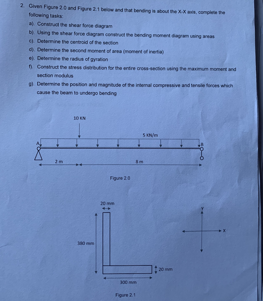
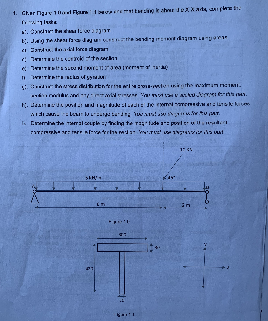
1. Given Figure 1.0 and Figure 1.1 below and that bending is about the X-X axis, complete the following tasks: a). Construct the shear force diagram b). Using the shear force diagram construct the bending moment diagram using areas c). Construct the axial force diagram d). Determine the centroid of the section e). Determine the second moment of area (moment of inertia) f). Determine the radius of gyration g). Construct the stress distribution for the entire cross-section using the maximum moment, section modulus and any direct axial stresses. You must use a scaled diagram for this part. h). Determine the position and magnitude of each of the internal compressive and tensile forces which cause the beam to undergo bending. You must use diagrams for this part. i). Determine the internal couple by finding the magnitude and position of the resultant compressive and tensile force for the section. You must use diagrams for this part. 5 KN/m 420 8 m SE53 181 Anbyens bet Figure 1.0 300 20 Figure 1.1 30 45 10 KN 2 m 2. Given Figure 2.0 and Figure 2.1 below and that bending is about the X-X axis, complete the following tasks: a). Construct the shear force diagram b). Using the shear force diagram construct the bending moment diagram using areas c). Determine the centroid of the section d). Determine the second moment of area (moment of inertia) e). Determine the radius of gyration f). Construct the stress distribution for the entire cross-section using the maximum moment and section modulus g). Determine the position and magnitude of the internal compressive and tensile forces which cause the beam to undergo bending 2 m 10 KN 380 mm Figure 2.0 20 mm 300 mm Figure 2.1 5 KN/m 8 m 20 mm
Step by Step Solution
3.42 Rating (155 Votes )
There are 3 Steps involved in it
To solve the problem given in Figure 10 and Figure 11 follow these steps based on the provided format a Construct the Shear Force Diagram 1 Calculate ... View full answer

Get step-by-step solutions from verified subject matter experts