

Question: Note: RL = R5 LT Spice the Emitter-Follower Amplifier Simulation 3. Wire the circuit of Figure 5 in LT Spise window. Use VSIN voltage source
Note: RL = R5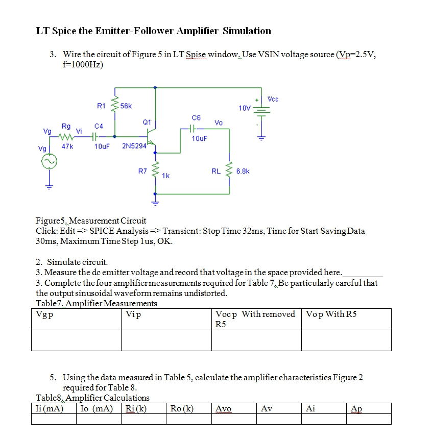
LT Spice the Emitter-Follower Amplifier Simulation 3. Wire the circuit of Figure 5 in LT Spise window. Use VSIN voltage source (Vp-2.5V, f-1000Hz) +Vcc R1 56k C6 QT Vo Rg Vi 10uF 10uF 2N5294 Vg47k R7 RL 6.8k 1k Figures Measurement Circuit Click: Edit>SPICE Analysis>Transient: Stop Time 32ms, Time for Start Saving Data 30ms, Maximum Time Step lus, OK. 2. Simulate circuit. 3. Measure the dc emitter voltage andrecord that voltage in the space provided here 3. Complete the four amplifiermeasurements required for Table 7.Be particularly careful that the output sinusoidal waveformremains undistorted Table7, Amplifier Measurements Vgp Vocp With removed Vop WithR5 R5 Using the data measured in Table 5, calculate the amplifier characteristics Figure 2 required for Table 8 5. Table8. Amplifier Calculations li (mA Io (mA)Ri(k Ro (k) Avo Av
Step by Step Solution
There are 3 Steps involved in it

Get step-by-step solutions from verified subject matter experts