

Question: NOTE: Shear Wall load shown is LRFD loading and includes the seismic load due to the weight of the shear wall line. GIVEN: detail at
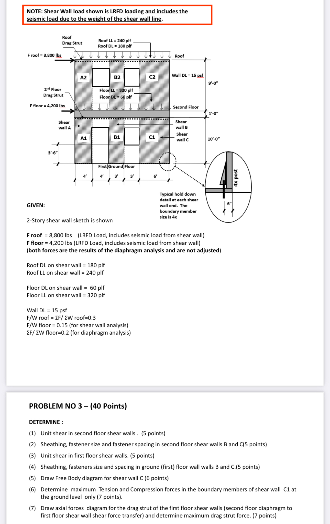
NOTE: Shear Wall load shown is LRFD loading and includes the seismic load due to the weight of the shear wall line.
GIVEN:
detail at each shear wall end. The boundary member
Story shear wall sketch is shown size is x
F roof LRFD Load, includes seismic load from shear wall
F floor lbs LRFD Load, includes seismic load from shear wallboth forces are the results of the diaphragm analysis and are not adjusted
Roof DL on shear wall plf
Roof LL on shear wall plf
Floor DL on shear wall plf
Floor LL on shear wall plf
Wall DL psf
FW roof roof
FW floor for shear wall analysis
EF WW floorfor diaphragm analysis
PROBLEM NO Points
DETERMINE:
Unit shear in second floor shear walls points
Sheathing, fastener size and fastener spacing in second floor shear walls and points
Unit shear in first floor shear walls. points
Sheathing, fasteners size and spacing in ground first floor wall walls and points
Draw Free Body diagram for shear wall C points
Determine maximum Tension and Compression forces in the boundary members of shear wall C at the ground level only points
Draw axial forces diagram for the drag strut of the first floor shear walls second floor diaphragm to first floor shear wall shear force transfer and determine maximum drag strut force. points
Step by Step Solution
There are 3 Steps involved in it
1 Expert Approved Answer
Step: 1 Unlock

Question Has Been Solved by an Expert!
Get step-by-step solutions from verified subject matter experts
Step: 2 Unlock
Step: 3 Unlock