

Question: On Ecampus under the Submit Homework menu option, submit a jpg or png image of your logic circuit and the . cpp source code file
On Ecampus under the "Submit Homework" menu option, submit a jpg or png image of your logic circuit and the cpp source code file for your program.
In data communications, parity is sometimes used to detect transmission errors. Assume for each byte transmitted, an extra parity bit is transmitted that is set to whether the byte has and even or odd number of s Using even parity, if the number of s is even, then the parity bit is set to If the number of s is odd, then the parity bit is set to
tabletableTransmittedBytetableCount ofsParity Bit
If the parity bit does not match the number of s in the byte, then there is an error.
tabletableTransmittedByteParity Bit,Errorfalsetruefalsetrue
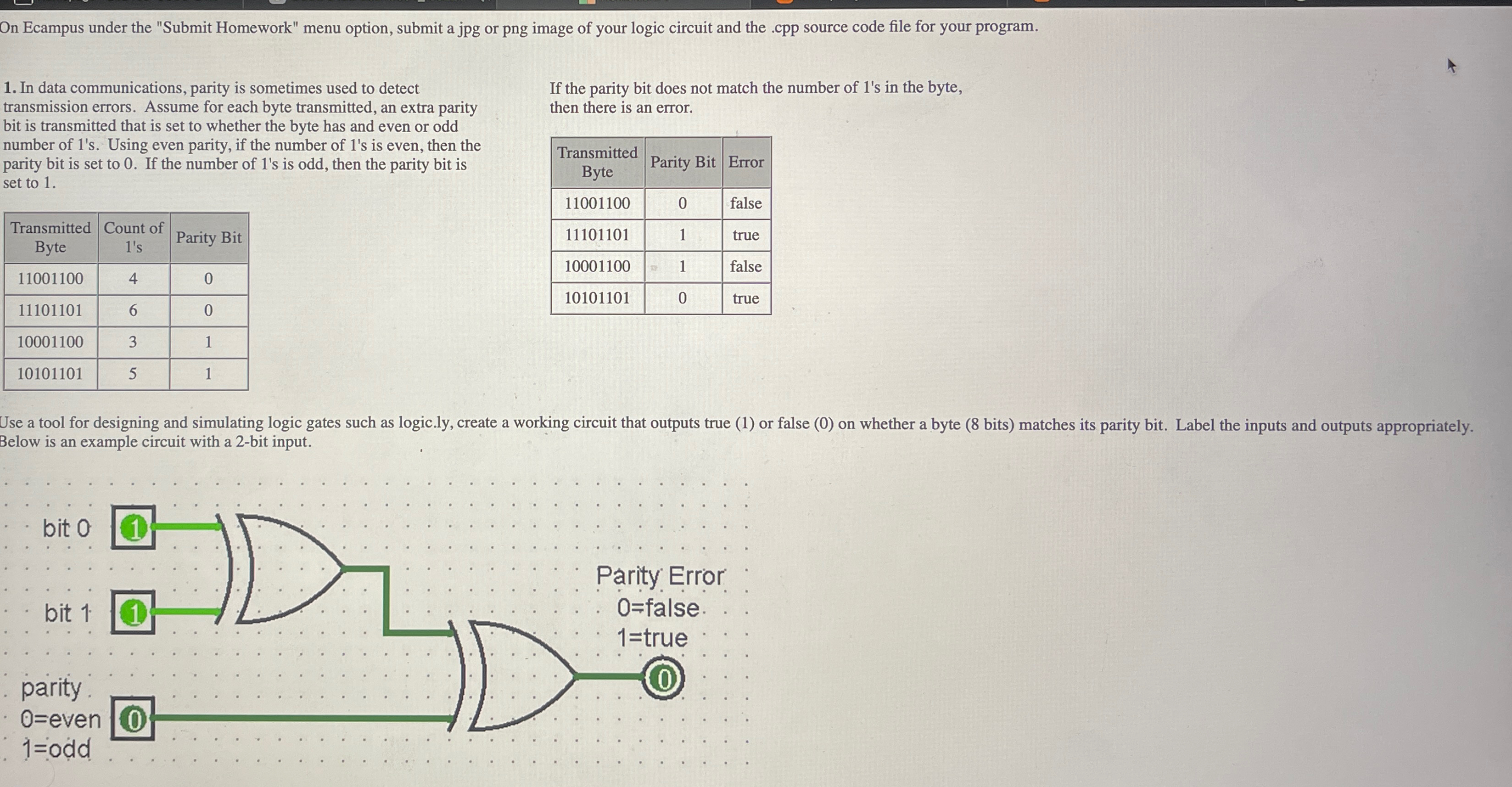
Use a tool for designing and simulating logic gates such as
logic.ly create a working circuit that outputs true or false on whether a byte bits matches its parity bit. Label the inputs and outputs appropriately. Below is an example circuit with a bit input.
Step by Step Solution
There are 3 Steps involved in it
1 Expert Approved Answer
Step: 1 Unlock

Question Has Been Solved by an Expert!
Get step-by-step solutions from verified subject matter experts
Step: 2 Unlock
Step: 3 Unlock