

Question: only two wires can be input into the and and or gates 1 7-Segment Decoder 1.1 Problem description In many applications of digital systems (clocks,
only two wires can be input into the "and" and "or" gates
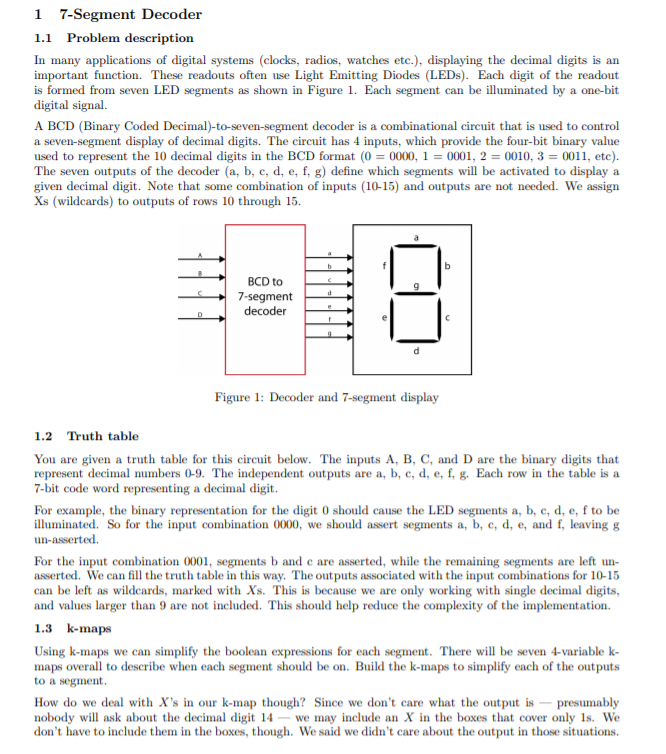
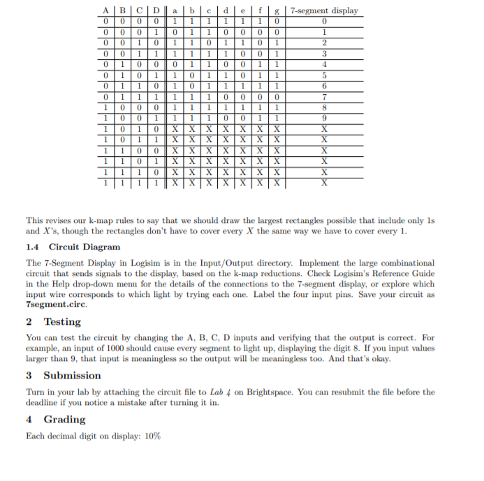
1 7-Segment Decoder 1.1 Problem description In many applications of digital systems (clocks, radios, watches etc.), displaying the decimal digits is an important function. These readouts often use Light Emitting Diodes (LEDs). Each digit of the readout is formed from seven LED segments as shown in Figure 1. Each segment can be illuminated by a one-bit digital signal. A BCD (Binary Coded Decimal)-to-seven-segment decoder is a combinational circuit that is used to control a seven-segment display of decimal digits. The circuit has 4 inputs, which provide the four-bit binary value used to represent the 10 decimal digits in the BCD format (0 = 0000, 1 = 0001, 2 = 0010, 3 = 0011, etc). The seven outputs of the decoder (a, b, c, d, e, f, g) define which segments will be activated to display a given decimal digit. Note that some combination of inputs (10-15) and outputs are not needed. We assign Xs (wildcards) to outputs of rows 10 through 15. b d BCD to 7-segment decoder B 1 Figure 1: Decoder and 7-segment display 1.2 Truth table You are given a truth table for this circuit below. The inputs A, B, C, and D are the binary digits that represent decimal numbers 0-9. The independent outputs are a, b, c, d, e, f, g. Each row in the table is a 7-bit code word representing a decimal digit. For example, the binary representation for the digit 0 should cause the LED segments a, b, c, d, e, f to be illuminated. So for the input combination 0000, we should assert segments a, b, c, d, e, and f, leaving & un-asserted. For the input combination 0001, segments b and c are asserted, while the remaining segments are left un- asserted. We can fill the truth table in this way. The outputs associated with the input combinations for 10-15 can be left as wildcards, marked with Xs. This is because we are only working with single decimal digits, and values larger than 9 are not included. This should help reduce the complexity of the implementation. 1.3 k-maps Using k-maps we can simplify the boolean expressions for each segment. There will be seven 4-variable k- maps overall to describe when each segment should be on. Build the k-maps to simplify each of the outputs to a segment. How do we deal with X's in our k-map though? Since we don't care what the output is - presumably nobody will ask about the decimal digit 14 - we may include an X in the boxes that cover only 1s. We don't have to include them in the boxes, though. We said we didn't care about the output in those situations. bolle B 0 0 0 0 0 0 0 0 0 1 0 1 0 1 0 1 1 0 1 0 1 0 1 0 1 1 1 1 1 1 1 D 0 0 0 1 1 0 1 1 0 0 0 1 1 0 1 1 0 0 0 1 1 0 1 1 0 0 0 1 10 1 a b c d e f 1 1 1 1 1 1 0 0 11 0 00 0 1 1 0 1 10 1 1 1 1 1 0 0 1 0 1 1 0 0 1 1 1 0 1 1 0 1 1 1 0 1 1 1 1 1 1 1 1 0 0 0 0 1 1 1 1 1 1 1 1 1 1 0 0 1 1 X X X X XX XXXX XX XXXX XXX X X X X X X X xxxxxx 7-segment display 0 1 2 3 4 5 6 7 8 9 X X X This revises our k-map rules to say that we should draw the largest rectangles possible that include only ls and X's, though the rectangles don't have to cover every X the same way we have to cover every 1. 1.4 Circuit Diagram The 7-Segment Display in Logisim is in the Input/Output directory. Implement the large combinational circuit that sends signals to the display, based on the k-map reductions. Check Logisim's Reference Guide in the Help drop-down menu for the details of the connections to the 7-segment display, or explore which input wire corresponds to which light by trying each one. Label the four input pins. Save your circuit as 7segment.circ. 2 Testing You can test the circuit by changing the A, B, C, D inputs and verifying that the output is correct. For example, an input of 1000 should cause every segment to light up, displaying the digit 8. If you input values larger than 9, that input is meaningless so the output will be meaningless too. And that's okay. 3 Submission Turn in your lab by attaching the circuit file to Lab 4 on Brightspace. You can resubmit the file before the deadline if you notice a mistake after turning it in. 4 Grading Each decimal digit on display: 10%
Step by Step Solution
There are 3 Steps involved in it

Get step-by-step solutions from verified subject matter experts